Operating manual (Rel. 1.1) Oxygen 7 Broadcast Console Via Caduti Di Sabbiuno 6/F • 40011 Anzola Emilia • Bologna • Italy ( +39 051 736555 • Fax. +39 051 736170 e-mail: info@axeltechnology.com • web site: www.axeltechnology.
Oxygen 7 - TABLE OF CONTENTS PART I: INPUT MODULES 1 TABLE OF CONTENTS 1 TABLE OF CONTENTS........................................................................................................................................2 2 SAFETY INSTRUCTIONS....................................................................................................................................4 3 CONNECTING MAINS POWER...................................................................................................
Oxygen 7 - TABLE OF CONTENTS 8.2 8.3 8.4 8.5 8.6 8.7 8.8 8.9 8.10 8.11 8.12 8.13 8.14 8.15 8.16 8.17 8.18 8.19 8.20 8.21 8.22 9 INTERFACE PIN-OUT.................................................................................................................................. 28 BLOCK DIAGRAM....................................................................................................................................... 29 INTRODUCTION ...................................................................
Oxygen 7 - SAFETY INSTRUCTIONS 2 SAFETY INSTRUCTIONS Read instructions: Retain these safety and operating instructions for future reference. Adhere to all warnings printed here and on the console power unit. Follow the operating instructions printed in this operating manual. Do not remove covers: Operate the power unit with its covers correctly fitted. Refer any service work to competent technical personnel only.
Oxygen 7 - CONNECTING MAINS POWER 3 CONNECTING MAINS POWER WARNING: Make sure the power supply voltage is correctly set to match your local mains voltage. Refer to the Power Supply Chapter in this operating manual. Before connecting the Oxygen 7 to mains power, determine the actual mains voltage and confirm that the Oxygen 7 has been configured correctly. As could be expected, an incorrect mains configuration could seriously damage the unit.
Oxygen 7 - CONNECTING MAINS POWER Have your mains system checked by a qualified electrician. Do not remove the earth connection from the console mains plug: The console chassis is connected to mains earth through the power cable to ensure your safety. Audio 0V (GND) is connected to the console chassis internally. If problems are encountered with earth loops disconnect the cable screens at one end, usually at the destination. Equipment such as CD players do not have a mains ground connection.
Oxygen 7 - SYSTEM OVERVIEW 4 SYSTEM OVERVIEW Oxygen 7 quality. The Oxygen 7 is a specially designed On-Air broadcast console. Although the design has been carefully budgeted, no compromises has been made in either quality or features, particularly in the areas of VCA control, switching, signalling, fader start/stop and communication. Most all of the switches have led indicators and all similar functions are grouped and colour coded, with additional fader knobs with different channel colour coding.
Oxygen 7 - AUDIO CONNECTIONS 5 AUDIO CONNECTIONS Matching the Console to Destination Equipment. The console produces a standard XLR output level of 0dBu for a meter reading of ‘0’. It can produce a maximum of +23dBu and is therefore well suited to driving equipment operating at nominal 0dBu or +4dBu while providing plenty of headroom. If you are connecting directly to a sensitive power amplifier it is advisable to turn down its input trim control if the normal console level is too high.
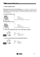
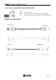
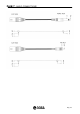
Oxygen 7 - AUDIO CONNECTIONS ¼” JACK PLUG CONNECTORS FOR INSERT SOCKETS Pin Ground Ring Tip Common Ground Channel audio return (inserted from external equipment) Channel audio output (to be provided to the external equipment) EXAMPLE OF CONNECTIONS Pag.
Oxygen 7 - AUDIO CONNECTIONS Pag.
Oxygen 7 - VCA & DUCK INTRODUCTION 6 VCA & DUCK INTRODUCTION 3 Analogies The acronym VCA stands for Voltage Controlled Amplifier, an electronic device that passes audio signal with its gain controlled by an external DC voltage. Each mixer channel is fitted with several VCA devices which replaces the conventional fader and audio switcher (MST/Sub routing, Stereo Mode switchers, etc) circuits. No audio passes through the fader and the switchers, as it does in the non-VCA consoles.
Oxygen 7 - MONO MODULE 7 MONO MODULE 7.1 MONO MODULE - REMOTE CONNECTOR The 9 pin D-Type plug remote connector provides the inputs and outputs for the following functions : • • • • • Remote Start / Stop for equipment connected to Input A Remote Start / Stop for equipment connected to Input B External Talkback Control Remote control for the channel On/Off External Duck Control A 6 VDC ± 50 mV current-limited output is also provided for use with the remote control inputs. 7.1.
Oxygen 7 - MONO MODULE 7.1.4 DUCK Control Pins 3, 6 and 1 allow remote control of the VCA fader circuits using an external linear potentiometer (10k ohm) connected across the + 6 V output and the GND input terminals. + 6 V at the pin 3 input yields 0 dB attenuation and 0 V yields the maximum attenuation. This control will affect each channel having ‘DUCK’ switcher pressed. DIRECT DUCK switcher on the MASTER module must be also pressed. 7.1.
Oxygen 7 - MONO MODULE 7.1.6 INTERFACE PIN-OUT SUB D 9P FEMALE 7.1.
Oxygen 7 - MONO MODULE 7.2 BLOCK DIAGRAM Pag.
Oxygen 7 - MONO MODULE 7.3 INTRODUCTION Each MONO module has two selectable mono inputs which comes factory preset for Mic (input A) and Line (input B) levels. Normally input A is selected but by pressing B SEL button the alternative input is selected. There are individual preset gain adjustements for each of A and B input with multi-turn controls and the selected source is fed through a phase switch and a common gain trim control giving a further ± 10dB of gain adjustment on the front panel.
Oxygen 7 - MONO MODULE 7.4 INPUT STAGE The A Input is via a standard female XLR-3 connector and it is set for MICROPHONE sources. The input is electronically balanced and it is factory-preset for a micro level. The recessed GAIN A trimmer allows you to adjust the gain in a large range. In conjunction with the GAIN potentiometer (see) this allows you to adjust the overall gain to any desired figure within the available range. The A PHANTOM jumper on the jumper bay (see § 7.
Oxygen 7 - MONO MODULE The same switch enables Remote Start A or B (see Remote Interface description) accordingly to the selected Input. I.e. only one of the two controls (Input A Start/Stop or Input B Start/Stop) will be active at any time, depending upon the setting of the B SEL switch 7.
Oxygen 7 - MONO MODULE 7.7 MODULE OPTIONS AND JUMPER SETTINGS The MONO module can be configured in a number of different ways depending on the jumper options set on the JUMPER SET bay: When closed, the A PHANTOM jumper allows for Phantom power on Input A When using a phantom powered microphone, ensure that the mixer is switched off when the microphone is plugged in to the XLR connector. When closed, the LIMITER jumper enables a Limiter internal stage.
Oxygen 7 - MONO MODULE When the C.ROOM MUTE jumper is closed, the action of moving the fader away from its down position is associated to the cut-off (or the selective fading) of the C.ROOM SPK output on the MONITOR module. CUT led on the MONITOR Ctrl Room section illuminates accordingly. When the STUDIO MUTE jumper is closed, the action of moving the fader away from its down position is associated to the cut-off (or the selective fading) of the STUDIO SPK output on the MASTER module.
Oxygen 7 - MONO MODULE 7.10 EQUALISER The Equaliser(EQ) comprises four sections. The upper control provides H.F.(treble) boost and cut of +/-15dB and the lower control provides L.F. (bass) boost and cut of +/-15dB. The centre two knobs is arranged as MID frequency section, with a cut/boost control (lower knob) of +/- 15dB, and a frequency control which determines at which frequency the boost/cut action will be centered.
Oxygen 7 - MONO MODULE 7.13 MASTER-SUB1-SUB2 ROUTING SWITCHES The input channel signal may be routed to the main Stereo MIX (L-R) or pairs SUB busses 1 & 2 by pressing the respective switches. The routing switchers work in conjunction with the module status (On or Off) There is a red LED next to each switch which will illuminate at two levels of brightness. The LED will illuminate at half brightness if the Switch is pressed but the module is Off.
Oxygen 7 - MONO MODULE To make it active the On status must be engaged (see § 7.16). The LED will illuminate at full brightness to indicate that the circuit is now active. When the switch is depressed, LED is off and the circuit is never active, regardless of the module status (On/Off). LED OFF switch depressed / the status of the module doesn’t affect routing circuit LED ON switch pressed / DUCK circuit is active as the module is On LED HALF BRIGH.
Oxygen 7 - MONO MODULE 7.16 START button The START button is used to start and stop a remote piece of equipment, as well as working in conjunction with the fader open signal to allow output from the channel. Each press of the START button will alternately send Start and Stop signals (See Remote Interface § 7.1). The LED illuminates accordingly. Two Start operating mode are given: When FADER Ù START jumper is closed (see § 7.
Oxygen 7 - MONO MODULE 7.18 FADER The fader is an ultra smooth 100 mm ALPS K-Series model controlling the internal high quality VCA circuity. There is no audio going through the faders which guarantees noise free fading for ever! (see Chapter 6). When the fader is closed, the signal is automatically muted, providing a cut-off in excess of 100 dB. This high dB cut-off value ensures that the main output is protected from crosstalk from announcers or fast spooling tape decks. The scale shows the attenuation.
Oxygen 7 - MONO MODULE 7.20 ALIGNEMENT OF INPUTS When plugging in a new source start with the channel muted or fader turned down and the Cue activated. This prevents any unexpected signal in the loudspeakers. The signal is displayed on the main CUE meter providing finer resolution and dynamic indication. Adjust the channel GAIN control for an average channel meter reading of ‘0’ with loud moments lighting ‘+3’. Adjust the Gain trimmers if the signal is still too high with gain turned down.
Oxygen 7 - STEREO MODULE 8 STEREO MODULE 8.
Oxygen 7 - STEREO MODULE 8.
Oxygen 7 - STEREO MODULE 8.3 BLOCK DIAGRAM Pag.
Oxygen 7 - STEREO MODULE 8.4 INTRODUCTION Each STEREO module has two selectable stereo inputs which comes factory preset for Line (input A) and Line (input B) levels or Line (input A) and Phono/RIAA (input B) levels, depending on the customer requirement. Normally input A is selected but by pressing B SEL button the alternative input is selected. There is individual preset gain adjustement for A input via jumpers (see 8.
Oxygen 7 - STEREO MODULE 8.5 INPUT STAGE The A Stereo Input is via standard female XLR-3 connectors and it is set for LINE sources. The input is electronically balanced and it is factorypreset for a 0 dB level (ref to § 8.8 for Sensibility adjustement). The B Stereo Input is via standard Jack ¼” sockets and it is set for signals providing a signal LINE level. The input is electronically balanced and factory-preset for a 0 dB level.
Oxygen 7 - STEREO MODULE 8.7 REMOTE interface This 15P SUB D FEMALE connector allows you to implement the following facilities: • • • • • • Remote Start for equipment connected to Input A Remote Stop for equipment connected to Input A Remote Start for equipment connected to Input B Remote Stop for equipment connected to Input B Remote PFL enable Remote Start/Stop control The Connettors provides also +6VDC and GND conections.
Oxygen 7 - STEREO MODULE When START Ù FADER jumper is closed, press START button to activate the module and provide a START command. Press START again to deactivate it. ON/OFF status of the module is regardless of the Fader position. When the START switch is not activated, the channel fader can be opened without bringing the audio up and without generating a start command. The channel can now be activated, by pressing the START switch (ON red led will glow).
Oxygen 7 - STEREO MODULE 8.10 MODE switches With both left and right switches activated, the stereo signal will be mixed to mono on both outputs. With only Mono L. activated, the left signal will be sent to both left and right signal paths. With only Mono R. activated, the right signal will be sent both left and right signal paths. In the 'Stereo' mode, neither Mono L. or Mono R. switches need to be activated. 8.11 EQUALISER The Equaliser(EQ) comprises three sections. The upper control provides H.F.
Oxygen 7 - STEREO MODULE channel fader, and therefore follows any changes in fader level. It is normally used to drive effects processing units which are fed back into the mixer and which must fade out with the input channel. The channels `START' switch will NOT switch the Auxiliary send on or off when it is set post fader. 8.13 BALANCE It adjusts the balance between the L and R outputs. At the detented centre position the signal routes equally to L and R. 8.
Oxygen 7 - STEREO MODULE 8.15 DUCK SWITCH The Duck is an ON/OFF switch which tells each VCA fader whether or not they partecipate in the external Duck control. Please ref to Chapter 6. The DUCK switcher works in conjunction with the module status (On or Off) There is a red LED next to the switch which will illuminate at two levels of brightness. The LED will illuminate at half brightness if the switch is pressed but the module is Off.
Oxygen 7 - STEREO MODULE The PFL signal can be heard by way of external headphones and amplifiers with loudspeaker connected to the Control Room and / or Studio sections – please refer to § Master and Monitor module descriptions.
Oxygen 7 - STEREO MODULE 8.18 ON LED It will glow when the channel is in the ON / START status (ref to § 7.16). 8.19 FADER The fader is an ultra smooth 100 mm ALPS K-Series model controlling the internal high quality VCA circuity. There is no audio going through the faders which guarantees noise free fading for ever! (see Chapter 6). When the fader is closed, the signal is automatically muted, providing a cut-off in excess of 100 dB.
Oxygen 7 - STEREO MODULE 8.20 Detect LED The Detect LED illuminates when a signal > - 30 dB is present on the selected input (A or B). The control is performed PRE-FADER. 8.21 ALIGNEMENT OF INPUTS When plugging in a new source start with the channel muted or fader turned down and the Cue activated. This prevents any unexpected signal in the loudspeakers. The signal is displayed on the main CUE meter providing finer resolution and dynamic indication.
Oxygen 7 - TELCO MODULE 9 TELCO MODULE 9.1 TELCO MODULE - REMOTE CONNECTOR The 9 pin D-Type plug remote connector provides the inputs and outputs for the following functions: • • Remote control for line ‘hooking’ on the external telephone hybrid External control for RING LED (i.e. RING LED on the Telco module can be driven by a suitable external command) A 15 VDC current-limited output is also provided for use with the remote control outputs. 9.1.
Oxygen 7 - TELCO MODULE It may be necessary to consult the hybrid manufacturer’s user manual in order to control its functions. OXYGEN 7 Telco remote interface has been designed for direct connection to BOXTEL and MACROTEL 5 / 7 / 9 by Axel Technology. A regular, not crossed Pin – to – Pin 9 pole cable featuring standard RS232 connectors is required for Boxtel connection (9 pin serial connection computer type). Pag.
Oxygen 7 - TELCO MODULE 9.2 INTRODUCTION This module controls the connection to the telephone external hybrid unit and has EQ, coarse and fine gain control, PFL and Master, Sub1 and Sub 2 output select. It has only one mono input, the other XLR connector being used for the output (mix minus) to the telephone hybrid. The presenter can talk off-air with a caller whilst the programme is being output through the TB to STUDIO audio path.
Oxygen 7 - TELCO MODULE 9.3 INPUT / OUTPUT STAGE The RECEIVE is via a standard female XLR-3 connector and it is set for line sources. The input is electronically balanced. The recessed GAIN trimmer allows you to adjust the gain in a large range. In conjunction with the GAIN potentiometer (see) this allows you to adjust the overall gain of Receive signal to any desired figure within the available range. The trimmer is acting only with AMPLIFIER jumper closed (see).
Oxygen 7 - TELCO MODULE 9.6 MODULE OPTIONS AND JUMPER SETTINGS The TELCO module can be configured in a number of different ways depending on the jumper options set on the JUMPER SET area: When closed, the AMPLIFIER jumper allows for extra-amplification on Receive signal. The recessed trimmer allows You to adjust the level. When closed, the LIMITER jumper enables a Limiter internal stage. The purpose of the limiter is to provide control over the hottest peaks in the signal.
Oxygen 7 - TELCO MODULE relay may be used to control an On Air Lamp (such as MR. LIGHT by Axel Technology). When the RELAY 2 jumper is closed, relay switch #2 inside the Power Supply closes when the fader is moved away from its down position. This relay may be used to control an On Air Lamp (such as MR. LIGHT by Axel Technology). 9.7 SEND level control It adjusts in the +/- 10 dB range the level of mix-minus signal which is sent to the telephone caller via the external telephone hybrid. 9.
Oxygen 7 - TELCO MODULE 9.9 EQUALISER The Equaliser (EQ) comprises four sections. The upper control provides H.F.(treble) boost and cut of +/-15dB and the lower control provides L.F. (bass) boost and cut of +/-15dB. The centre two knobs is arranged as MID frequency section, with a cut/boost control (lower knob) of +/- 15dB, and a frequency control which determines at which frequency the boost/cut action will be centered.
Oxygen 7 - TELCO MODULE 9.11 PAN The PAN control determines the position of the signal within the stereo mix image. Rotation fully anticlockwise feeds the signal solely to the Left mix bus (Master, Sub 1 & Sub 2 outputs), while rotation clockwise sweeps the image to the Right mix bus (Master, Sub 1 & Sub 2 outputs). The centre applies 0dB of gain to both signals. 9.
Oxygen 7 - TELCO MODULE 9.13 DUCK SWITCH The Duck is an ON/OFF switch which tells each VCA fader whether or not they partecipate in the external Duck control. Please ref to Chapter 6. The DUCK switcher works in conjunction with the module status (On or Off) There is a red LED next to the switch which will illuminate at two levels of brightness. The LED will illuminate at half brightness if the switch is pressed but the module is Off.
Oxygen 7 - TELCO MODULE to Mono module (and routed as TB to Studio – see § 7.7).
Oxygen 7 - TELCO MODULE 9.16 ON LED It will glow when the channel is in the ON status (i.e. the fader is moved away from its down position). 9.17 FADER The fader is an ultra smooth 100 mm ALPS K-Series model controlling the internal high quality VCA circuity. There is no audio going through the faders which guarantees noise free fading for ever! (see Chapter 6). When the fader is closed, the signal is automatically muted, providing a cut-off in excess of 100 dB.
Oxygen 7 - TELCO MODULE 9.18 Detect LED The Detect LED illuminates when a signal > - 30 dB is present on the selected input (A or B). The control is performed PRE-FADER. 9.19 ALIGNEMENT OF INPUTS When plugging in a new source start with the channel muted or fader turned down and the Cue activated. This prevents any unexpected signal in the loudspeakers. The signal is displayed on the main CUE meter providing finer resolution and dynamic indication.