
User manual


MACROTEL X1 - MACROTEL X2 CONNECTION PROCEDURE
| MACROTEL X1 - MACROTEL X2 CONNECTION PROCEDURE
48
16.4 WIRELESS CONNECTION VIA GSM MODULE 1 AND GSM MODULE 2
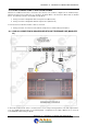
Up to two GSM devices can be connected to Macrotel X1 and Macrotel X2 with mute exchange between the
POTS/PSTN line and the GSM line. See the LINE TYPE section for the mute exchange of this line. The image below
shows how to connect the GSM-1 AND GSM-2 modules.
Cable A-1 is an Audio cable with an RJ10 on one end directly connected to the “GSM” port of LINE 1 of the Macrotel
X1.
Cable B-1 is of the “data” Cross type with SubD 9 pin Male/Male connection to the GSM Module-1 and to the RS232-1
port of the Macrotel X1.
Cable A-1 is an Audio cable with an RJ10 on one end directly connected to the “GSM” port of LINE 1 of the Macrotel
X2. Cable B-1 is of the “data” Cross type with SubD 9 pin Male/Male connection to the GSM Module-1 and to the
RS232-1 port of the Macrotel X2.
Cable A-2 is an Audio cable with an RJ10 on one end directly connected to the “GSM” port of LINE 2 of the Macrotel X2.
Cable B-2 is of the “data” Cross type with SubD 9 pin Male/Male connection to the GSM Module-2 and to the RS232-2
port of the Macrotel X2.