
Installation guide

Installation
Installation Guide - Models 65B 3
2 - INSTALLATION
This chapter provides information and instructions to install the AX3000 Model
65B.
2.1 - DESCRIPTION
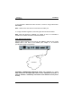
A green LED, located on the face plate, indicates when the AX3000 is powered
on.
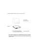
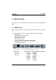
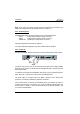
The AX3000 has the following connectors and switches on the rear panel:
- power switch,
- power connector for the AX3000,
- VGA or SVGA connector,
- PS/2 keyboard connector,
- PS/2 mouse connector,
- two auxiliary serial ports: RJ45 (AUX1 and AUX2),
- auxiliary parallel port: female 25-pin (PARALLEL),
- TCP/IP port: RJ45 (LAN).
8 9 1 2 3 4 5 6 7
On/Off Power inlet VGA Keyboard Mouse Serial1 Serial2 Parallel LAN
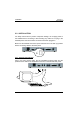
Power Inlet:
100 - 240 V~
0.2 - 0.1 A
50 - 60Hz
Safety Extra Low Voltages (SELV) Connectors:
1 - SVGA shielded
2 - Keyboard unshielded
3 - Mouse unshielded
4 - Serial1 shielded
5 - Serial2 shielded
6 - Parallel shielded
7 - LAN unshielded