
Technical data
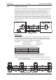


8.18 CANopen interface (X6)
The interface for connection to the CAN-bus (default : 500 kBaud). The integrated profile
is based on the CANopen DS301 communication profile and the DS402 drive profile.
The following functions are available in connection with the position controller:
Jogging with variable speed, homing run (zeroing to reference), start motion task, start
direct task, digital setpoint provision, data transmission functions and many others.
Detailed information can be found in the CANopen manual. The interface is at the same
electrical potential as the RS232 interface. The analog setpoint inputs can still be used.
With the optional -2CAN- expansion card, the two interfaces for RS232 and CAN, which
otherwise use the same connector X6, are separated out onto three connectors (with ter-
mination, ð p.123).
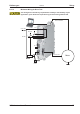
CAN-bus cable
To meet ISO 11898, a bus cable with a characteristic impedance of 120 W should be
used. The maximum usable cable length for reliable communication decreases with
increasing transmission speed. As a guide, you can use the following values which we
have measured, but they are not to be taken as assured limits:
Cable data: Characteristic impedance 100-120 W
Cable capacitance max. 60 nF/km
Lead loop resistance 159.8 W/km
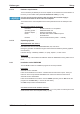
Cable length, depending on the transmission rate
Transmission rate (kBaud) max. cable length (m)
1000 10
500 70
250 115
Lower cable capacitance (max. 30 nF/km) and lower lead resistance
(loop resistance, 115 W/km) make it possible to achieve greater distances.
(Characteristic impedance 150 ± 5 WÞterminating resistor 150 ± 5 W).
For EMC reasons, the SubD connector housing must fulfill the following requirements:
— metal or metalized housing
— provision for cable shielding connection on the housing, large-area connection
S300 Instructions Manual 91
Kollmorgen 09/2011 Electrical installation
S300