
Technical data
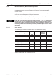
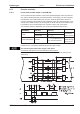
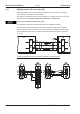

8.16.2 Digital inputs (X3/X4)
All digital inputs are electrically isolated via optocouplers.
Technical characteristics
— Ground reference is Digital-GND (DGND, terminals X4/3 and X4/4)
— The inputs at X3 are PLC-compatible (IEC 61131-2 Type 1)
High: 11...30 V / 2...11 mA , Low: -3...5V/<1mA
— Update rate Software:250 µs / Hardware: 2 µs
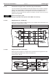
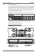
ENABLE input
The output stage of the servo amplifier is enabled by applying the ENABLE signal
(terminal X3/12, 24 V input, active high). Enable is possible only if input STO-Enable has
a 24 V signal (see page 35ff).
In the disabled state (low signal) the connected motor has no torque.
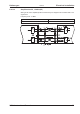
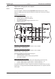
STO-ENABLE input
An additional digital input (STO-Enable) releases the power output stage of the amplifier
as long as a 24 V signal is applied to this input. If the STO-Enable input goes open-circuit,
then power will no longer be supplied to the motor, the drive will lose all torque and
coast down to a stop. A fail-safe brake function for the drive, if one is required, must be
ensured through a mechanical brake since electrical braking with the aid of the drive is no
longer possible.
You can thus achieve a restart lock-out for personnel safety by using the STO-Enable
input in conjunction with an external safety circuit.
You can find further information and connection examples on page 35.
The STO-Enable input is not compatible with IEC 61131-2.
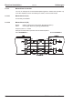
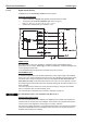
Programmable digital inputs
You can use the DIGITAL-IN1 to DIGITAL-IN4 digital inputs to initiate pre-programmed
functions that are stored in the servo amplifier. A list of these pre-programmed functions
can be found on the “Digital I/O” screen page of our setup software.
If an input was freshly assigned to a pre-programmed function, then the data set must be
saved in the EEPROM of the servo amplifier and a reset has to be carried out (with the
amplifier setup software for example).
88 S300 Instructions Manual
Electrical installation 09/2011 Kollmorgen
S300