
Technical data

8.15.2 SSI encoder output (X5)
The SSI interface (synchronous serial absolute-encoder emulation) is part of the standard
package. Select encoder function SSI (“Encoder Emulation” screen page, ENCMODE 2).
The servo amplifier calculates the motor shaft position from the cyclic-absolute signals of
the resolver or encoder. From this information a SSI date (Stegmann patent specification
DE 3445617C2) is provided. Max 32 bits are transferred. The leading data bit contains
the number of revolutions and are selectable from 12 to 16 bits. The following max. 16
bits contain the resolution and are not variable.
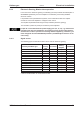
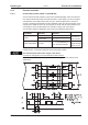
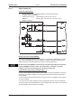
The following table shows the allocation of the SSI date depending upon selected number
of revolutions:
Revolution
Resolution (variable)
SSIREVOL
Bit
1514131211109876543210
1514131211109876543210
14131211109876543210
131211109876543210
1211109876543210
11109876543210
The signal sequence can be output in Gray code or in Binary (standard) code.
The servo amplifier can be adjusted to the clock frequency of your SSI-evaluation with the
setup software (cycle time 1,3 µs or 10 µs).
The drivers operate off an internal supply voltage.
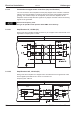
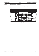
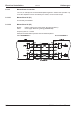
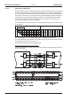
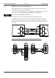
Connection and signals for the SSI interface :
Default count direction: UP when the motor shaft is rotating clockwise (looking at the end
of the motor shaft)
86 S300 Instructions Manual
Electrical installation 09/2011 Kollmorgen
S300