
Technical data

8.15 Encoder emulation
8.15.1 Incremental encoder output - A quad B (X5)
The incremental-encoder interface is part of the standard package. Select encoder func
-
tion ROD (A Quad B) Encoder (“Encoder Emulation” screen page). The servo amplifier
calculates the motor shaft position from the cyclic- absolute signals of the resolver or
encoder, generating incremental-encoder compatible pulses from this information. Pulse
outputs on the SubD connector X5 are 2 signals, A and B, with 90° phase difference (i.e.
in quadrature, hence the alternative term “A quad B” output), with a zero pulse.
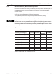
The resolution (before multiplication) can be set by the RESOLUTION function:
Enc. function
(ENCMODE)
Feedback system
(FBTYPE)
Resolution (lines)
(ENCOUT)
Zero pulse (NI)
1, ROD
0, Resolver 32...4096
once per turn
(only at A=B=1)
2,4 Encoder
256...524288
(2
8
... 2
19
)
3, ROD interpolation Encoder
2
4
…2
7
(multiplication) TTL
line x encoder resolution
encoder signal
passed through
from X1 to X5
Use the NI-OFFSET parameter to adjust + save the zero pulse position within one
mechanical turn. The drivers operate off an internal supply voltage.
The maximum permissible cable length is 100 meters.
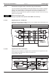
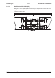
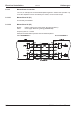
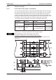
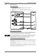
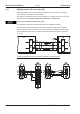
Connections and signals for the incremental encoder interface :
Default count direction: UP when the motor shaft is rotating clockwise (looking at the
shaft's end)
S300 Instructions Manual 85
Kollmorgen 09/2011 Electrical installation
S300