
Technical data

8.14 Electronic Gearing, Master-slave operation
In the case of the “electronic gearing” functionality (see setup software and description of
GEARMODE parameter), the servo amplifier is controlled by a secondary feedback
device as a slave.
It is possible to set up master/slave systems, use an external encoder as a setpoint
encoder or connect the amplifier to a stepper motor control.
The amplifier is parameterized using the setup software (electronic gearing).
The resolution (number of pulses per revolution) can be adjusted.
If input X1 is used without the X1 power supply (pins 2, 4, 10, 12), e.g. master-slave
operation with other servoamplifiers, the monitoring of this power supply must be
switched off in order to prevent error message F04 from appearing. To do this, you
must change Bit 20 of the DRVCNFG2 parameter (see ASCII object reference in the
online help).
8.14.1 Signal source
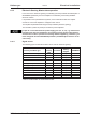
The following types of external encoders can be used for electronic gearing:
secondary Feedback type
Fre-
quency
limit
Connector
Wiring
diagram
GEARMODE
SinCos Encoder BiSS digital 1.5MHz X1
ð p.65
11, 12
SinCos Encoder ENDAT 2.1 350kHz X1
ð p.66
8
SinCos Encoder ENDAT 2.2 1.5MHz X1
ð p.67
13
SinCos Encoder HIPERFACE 350kHz X1
ð p.68
9
SinCos Encoder w/o data channel 350kHz X1
ð p.70
6, 7
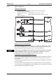
ROD* (AquadB) 5V 1.5MHz X1
ð p.72
30
ROD* (AquadB) 5V 350kHz X1
ð p.73
10
ROD* (AquadB) 5V 1.5MHz X5
ð p.75
3
ROD* (AquadB) 24V 100kHz X3
ð p.77
2
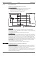
SSI 5V 1.5MHz X5
ð p.79
5
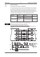
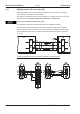
Step/direction 5V 1.5MHz X1
ð p.82
27
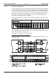
Step/direction 24V 100kHz X3
ð p.82
1
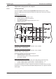
Step/direction 5V 1.5MHz X5
ð p.83
4
* ROD is an abbreviation for incremental encoder
S300 Instructions Manual 81
Kollmorgen 09/2011 Electrical installation