
Technical data
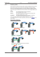
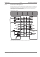


8.13 Primary and secondary feedback types
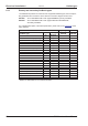
The table below provides an overview of the supported feedback types, their correspon
-
ding parameters and a reference to the relevant connection diagram in each case.
FBTYPE set on DRIVEGUI.EXE screen page FEEDBACK, primary Feedback
EXTPOS set on DRIVEGUI.EXE screen page POSITION CONTROLLER,
secondary Feedback
For a detailed description of the ASCII parameters, please refer to the online help
of the
setup software.
primary secondary
Feedback type
Connec-
tor
Wiring
diagram
FBTYPE EXTPOS
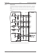
Resolver X2
ð p.63
0-
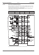
SinCos Encoder BiSS (B) analog X1
ð p.64
23, 24 -
SinCos Encoder BiSS (B, C) digital X1
ð p.65
20, 22, 33 11, 12
SinCos Encoder ENDAT 2.1 X1
ð p.66
4, 21 8
SinCos Encoder ENDAT 2.2 X1
ð p.67
32 -
SinCos Encoder HIPERFACE X1
ð p.68
29
SinCos Encoder SSI (linear) X5/X1
ð p.69
28 -
SinCos Encoder w/o data channel X1
ð p.70
1, 3, 7, 8 6, 7
SinCos Encoder + Hall X1
ð p.71
5, 6 -
ROD* 5V w/o zero, 1.5MHz X1
ð p.72
30, 31 30
ROD* 5V with zero X1
ð p.73
17,27 10
ROD* 5V with zero, with Hall X1
ð p.74
15 -
ROD* 5V with zero X5
ð p.75
13, 19 3
ROD* 5V with zero, with Hall X5/X1
ð p.76
18 -
ROD* 24V w/o zero X3
ð p.77
12, 16 2
ROD* 24V w/o zero, with Hall X3/X1
ð p.78
14 -
SSI X5
ð p.79
95
Hall X1
ð p.80
11 -
Sensorless (w/o Feedback) - - 10 -
Step/Direction 5V, 1.5 MHz X1
ð p.82
-27
Step/Direction 5V, 1.5 MHz X5
ð p.83
-4
Step/Direction 24V, 100 kHz X3
ð p.82
-1
* ROD is an abbreviation for “incremental encoder”.
62 S300 Instructions Manual
Electrical installation 09/2011 Kollmorgen