
Technical data
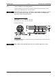

8.9 External brake resistor (X8)
Remove the plug-in link between the terminals X8/5 (-R
B
) and X8/4 (+R
bint
).
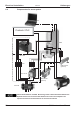
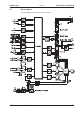
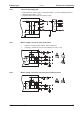
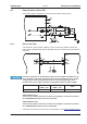
8.10 DC bus link (X8)
Terminals X8/1 (-DC) and X8/3 (+RBext). Can be connected in parallel, whereby the
brake power is divided between all the amplifiers that are connected to the same DC bus
link circuit.
The servo amplifiers can be destroyed, if DC bus link voltages are different. Only
servo amplifiers with mains supply from the same mains (identical mains supply
voltage) may be connected by the DC bus link. Use unshielded single cores
(2.5mm²) with a max. length of 200 mm. Use shielded cables for longer lengths.
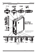
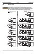
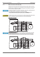
S701...724 with
HWR* < 2.00
S701...724 with
HWR* ³ 2.00
S300
S300
no
ÄÄ
*HWR = Hardware Revision (see nameplate)
SERVOSTAR 303-310
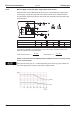
The sum of the rated currents for all of the servo amplifiers connected in parallel
to an SERVOSTAR 303-310 must not exceed 24 A.
SERVOSTAR 341-346
The sum of the rated currents for all of the servo amplifiers connected in parallel
to an SERVOSTAR 341-346 must not exceed 40A.
Information for fusing can be found in the "Product WIKI", check www.wiki-kollmorgen.eu
.
S300 Instructions Manual 59
Kollmorgen 09/2011 Electrical installation
S300
S300
S300