
Technical data
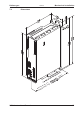

8.3 Wiring
The installation procedure is described as an example. A different procedure may be
appropriate or necessary, depending on the application of the equipments.
We provide further know-how through training courses (on request).
8.3.1 Safety instructions
There is a danger of electrical arcing with serious personal injury. Only install and
wire up the equipment when it is not live, i.e. when neither the electrical supply nor
the 24 V auxiliary voltage nor the supply voltages of any other connected
equipment is switched on.
Take care that the cabinet is safely disconnected (with a lock-out, warning signs
etc.). The individual voltages will be switched on for the first time during setup.
Only professional staff who are qualified in electrical engineering are allowed to
install the servo amplifier.
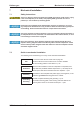
The ground symbol
X, which you will find in all the wiring diagrams, indicates
that you must take care to provide an electrically conductive connection with the
largest feasible surface area between the unit indicated and the mounting plate in
the control cabinet. This connection is for the effective grounding of HF
interference, and must not be confused with the PE-symbol W
(PE = protective earth, safety measure as per IEC 60204).
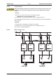
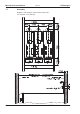
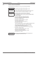
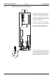
Use the following connection diagrams :
Safety Function STO : page 40
Overview : page 55
Mains power : page 57
Motor : page 60
Feedback : page 61ff
Electronic Gearing / Master Slave
Master-Slave : page 81
Pulse-Direction : page 82
Encoder Emulation
ROD (A quad B) : page 85
SSI : page 86
Digital and analog inputs and outputs : page 87ff
RS232 / PC : page 90
CAN Interface : page 91
Expansion cards
I/O-14/08 : page 114
PROFIBUS : page 115
SERCOS : page 117
DeviceNet : page 118
SynqNet : page 122
2CAN : page 124
Options
EtherCAT : page 125
FAN : page 126
EtherCAT&FAN : page 126
S300 Instructions Manual 49
Kollmorgen 09/2011 Electrical installation