
Technical data


6.9.8 Functional description
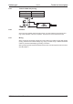
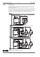
In case of use of the STO function the input STO-Enable must be connected to the exit of
a security control or a safety relay, which meets at least to therequirements of the SIL
CL2 according to IEC 62061 and PL d according to ISO 13849-1 (see the connection dia
-
gram on page 40).
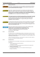
Possible states of the servo amplifier in connection with STO function:
STO-ENABLE ENABLE Display Motor has torque SIL CL2 / PL d
0 V 0 V -S- no yes
0 V +24 V F27 no yes
+24 V 0 V normal status e.g. 06 no no
+24 V +24 V normal status e.g. E06 yes no
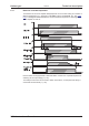
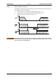
When STO function is engaged during operation by separating input STO-Enable
from 24 VDC, the motor runs down out of control and the servo amplifier displays
the error F27. There is no possibility of braking the drive controlled. If a controlled
braking before the use of the restart lock is necessary, the drive must be braked
and the input STO-ENABLE has to be separated from +24 VDC time-delayed.
Because restart lock is a single-channel system, erroneous engaging will not be
recognized. Therefore the output of the control must be supervised for possible
malfunction.
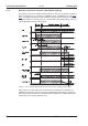
If the STO function is not needed in the application, then the input STO-ENABLE
must be connected directly with +24VDC. The STO function is passed by now and
cannot be used. The servo amplifier cannot be used as a safety component
referring to the EC Machine Directive now.
When wiring the input STO-ENABLE within one enclosure it must be paid attention to the
fact that the used cables and the enclosure meet the requirements of IEC 60204-1.
If the wiring leads outside the demanded enclosure, the cables must be laid durably
(firmly), and protected from outside damage (see chapter "Wiring").
38 S300 Instructions Manual
Technical description 09/2011 Kollmorgen