
Technical data

6.7 Switch-on and switch-off behavior
This chapter describes the switch-on and switch-off behavior of the S300 and the steps
required to achieve operational stopping or emergency stop behavior that complies with
standards.
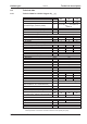
The servo amplifier’s 24 V supply must remain constant. The ASCII commands
ACTFAULT (error response) and STOPMODE (ENABLE signal response) dictate
how the drive will behave.
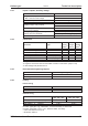
ACTFAULT /
STOPMODE
Behavior (see also ASCII reference in the online help
of the setup soft-
ware)
0
Motor coasts to a standstill in an uncontrolled manner
1 (default)
Motor is braked in a controlled manner
Behavior during a power failure
The servo amplifiers use an integrated circuit to detect if one or more input phases
(power supply feed) fail. The behavior of the servo amplifier is set using the setup soft-
ware: Under “Response to Loss of Input Phase” (PMODE) on the Basic Setup screen,
select:
l
Warning if the higher-level control system is to bring the drive to a standstill: War-
ning n05 is output if an input phase is missing, and the motor current is limited to 4 A.
The servo amplifier is not disabled. The higher-level control system can now selecti-
vely end the current cycle or start bringing the drive to a standstill. Therefore, the er-
ror message “MAINS BTB, F16" is output on a digital output of the servo amplifier
and evaluated by the control system, for instance.
l Error message if the servo amplifier is to bring the drive to a standstill: Error messa-
ge F19 is output if an input phase is missing. The servo amplifier is disabled and the
BTB contact opens. Where the factory setting is unchanged (ACTFAULT=1), the mo-
tor is braked using the set “EMERGENCY STOP RAMP”.
Behavior when undervoltage threshold is reached
If the undervoltage threshold is undershot in the DC bus link (the threshold value
depends on the type of servo amplifier), the error message “UNDERVOLTAGE, F05" is
displayed. The drive response depends on the ACTFAULT/STOPMODE setting.
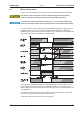
Behavior with enabled “holding brake” function
Servo amplifiers with an enabled holding brake function have a special procedure for
switching off the output stage ( ð p. 27). Removing the ENABLE signal triggers electrical
braking. As with all electronic circuits, the general rule applies that there is a possibility of
the internal “holding brake” module failing. Bringing a motor to a standstill using a holding
brake in a way that is personnel safe also requires an electromechanical “make” contact
for the holding equipment and a suppressor device for the brake.
Behavior of the safety function STO
With the personnel safe, certified safety function STO, the drive can be secured on stand-
still using its internal electronics so that even when power is being supplied, the drive
shaft is protected against unintentional restart. The chapter “Safety Function STO”
describes how to use the STO function. See page 35 onwards.
30 S300 Instructions Manual
Technical description 09/2011 Kollmorgen