
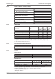
Technical data

6.3 Motor holding brake
A 24V / max.1.5A holding brake in the motor can be controlled directly by the amplifier.
This function does not ensure personnel safety! Hanging load (vertical axes)
require an additional mechanical brake which must be safely operated.
The brake only works with sufficient voltage level (ð p.25). Check voltage drop,
measure the voltage at brake input and check brake function (brake and no brake).
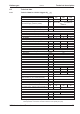
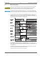
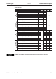
The brake function must be enabled through the BRAKE setting (screen page: Motor). In
the diagram below you can see the timing and functional relationships between the
ENABLE signal, speed setpoint, speed and braking force. All values can be adjusted with
parameters, the values in the diagram are default values.
During the internal ENABLE delay time of 100ms (DECDIS), the speed setpoint of the
servo amplifier is internally driven down an adjustable ramp to 0V. The output for the
brake is switched on when the speed has reached 5 rpm (VELO), at the latest after 5 sec-
onds (EMRGTO).
The rise (f
brH
) and fall (f
brL
) times of the holding brake that is built into the motor are dif-
ferent for the various types of motor (see motor manual).
A description of the interface can be found on page 60.
S300 Instructions Manual 27
Kollmorgen 09/2011 Technical description