
Technical data
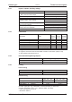

6.2.3 Inputs / outputs, Auxiliary voltage
Interface electr. data
Analog inputs 1, 2 (resolution 14/12 bit)
±10V
Max. common-mode voltage
±10V
Digital control inputs as per IEC 61131-2 Type 1, max. 30VDC
Digital control outputs, active high open Emitter, max. 30VDC, 10mA
BTB/RTO output, relay contacts
max. 30VDC, max 42VAC
500mA
Auxiliary supply voltage, electrically isolated,
without motor brake/fan
20V - 30V
1A
Auxiliary supply voltage, electrically
isolated, with motor brake/fan
24V (-0% +15%)
2.5A (check voltage drop !)
Min./max. output current to brake 0.15A / 1.5A
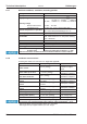
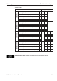
6.2.4 Connectors
Connector Type
max.
cross
section
*1
permit-
ted cur-
rent
*
2
permit-
ted ten-
sion
*3
Control signals X3, X4 Combicon connector 1,5mm² 4A 160V
S303-310 Power signals X0,X8,X9 Combicon connector 2,5mm² 12A 630V
S341-346 Power signals X0,X8,X9 Combicon connector 4mm² 16A 1000V
Resolver input X2 SubD 9-pin (socket) 0,5mm² 1A <100V
Encoder input X1 SubD 15-pin (socket) 0,5mm² 1A <100V
PC interface, CAN X6 SubD 9-pin (plug) 0,5mm² 1A <100V
Encoder emulation, ROD/SSI X5 SubD 9-pin (plug) 0,5mm² 1A <100V
*1 single-line connection
*2 single-line connection with recommended conductor cross section (chapt. 6.2.8)
*3 rated voltage with pollution level 2
6.2.5 Recommended tightening torques
Connector Tightening torque
X0, X8, X9 0.5..0.6 Nm
Grounding bolt 3.5 Nm
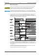
6.2.6 Fusing
Internal fusing
Circuit Internal fuse
Auxiliary voltage 24V 3.15 AT
Brake resistor electronic
External fusing
Wire fuses or similar
SERVOSTAR
303*, 341*, 343*
SERVOSTAR
306*, 310*, 346*
AC supply feed F
N1/2/3
(X0/1; 2; 3) 6 AT 10 AT
24V feed F
H1/2
max. 8 AF
Brake resistor F
B1/2
(X8/2; 4) 6 AT** 6 AT**
EU fuses: types gRL or gL, 400V/500V, T means time-delay, F means fast
US fuses: class RK5 or CC or J or T, 600VAC 200kA, time-delay
* order code reference see p. 20
** Bussmann FWP-xx
S300 Instructions Manual 25
Kollmorgen 09/2011 Technical description