
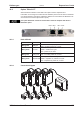
Technical data

11 Appendix
11.1 Glossary
B Brake circuit Converts superfluous energy fed back by the
motor during braking (regenerated energy) into
heat.
C Clock Clock signal
Common-mode voltage The maximum amplitude of a disturbance (on both
inputs) which a differential input can eliminate
Counts Internal count pulses, 1 pulse = 1/2
20
turn
-1
Continuous power of brake circuit Mean power that can be dissipated in the brake
circuit
Current controller Regulates the difference between the current
setpoint and the actual value to 0
Output : power output voltage
D DC bus link Rectified and smoothed power voltage
Disable Removal of the ENABLE signal
E Earth short electrical connection between a phase and
the protective earth (PE)
Enable Enable signal for the servo amplifier,
Hardware-Enable with 24V signal to X3,
Software-Enable command by setup Software,
fieldbus or permanently set.
Both are required for enabling the amplifier.
ENABLE Enable signal for the servo amplifier (+24 V)
F Fieldbus interface CANopen, PROFIBUS, SERCOS etc.
Final speed (limit speed) Maximum value for the speed normalization at
±10 V
G GRAY-code Special format for representing binary numbers
H Holding brake Brake in the motor, that can only be used when the
motor is at standstill
I I²t threshold Monitoring of the r.m.s. current that is actually
required
Input drift Temperature and age-dependent alteration of an
analog input
Incremental encoder interface Position signaling by 2 signals with 90° phase
difference (i.e. in quadrature), is not an absolute
position output
Ipeak, peak current The effective value of the peak current
Irms, effective current The r.m.s. value of the continuous current
K Kp, P-gain Proportional gain of a control loop
L Limit speed (final speed) Maximum value for speed normalization at ±10 V
Limit switch Switch limiting the traverse path of the machine;
implemented as n.c. (break) contact
S300 Instructions Manual 127
Kollmorgen 09/2011 Appendix