
Technical data
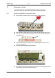
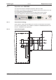
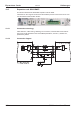


10.2.4 Connector assignments
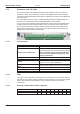
The functions are adjustable with the setup software. In the table below the default values
are described.
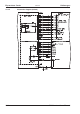
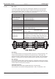
Connector X11A
Pin Dir
Default
function
Description
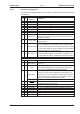
1 In A0 Motion block number, LSB
2 In A1 Motion block number, 2
1
3 In A2 Motion block number, 2
2
4 In A3 Motion block number, 2
3
5 In A4 Motion block number, 2
4
6 In A5 Motion block number, 2
5
7 In A6 Motion block number, 2
6
8 In A7 Motion block number, MSB
9 In Reference
Polls the home switch. If a digital input on the base unit is
used as a home input, then the input on the expansion card
will not be evaluated.
10 In F_error_clear
Clears the warning of a following error (n03) or the response
monitoring (n04)
11 In Start_MT_Next
The following task, that is defined in the motion task by “Start
with I/O” is started. The target position of the present motion
task must be reached before the following task can be started.
The next motion block can also be started by an appropriately
configured digital input on the base unit.
12 In Start_Jog v= x
Starts the "Jog Mode" with a defined speed. “x” is the speed
saved in the servo amplifier for the function "Jog Mode". A ri-
sing edge starts the motion, a falling edge cancels the motion.
Connector X11B
1 In MT_Restart Continues the motion task that was previously interrupted.
2 In Start_MT I/O
Starts the motion task that is addressed by A0-A7 (connector
X11A/1...8).
3 Out InPos
When the target position for a motion task has been reached
(the InPosition window), this is signaled by the output of a
HIGH signal. A cable break will not be detected.
4 Out
Next-InPos
The start of each motion task in an automatically executed
sequence of motion tasks is signaled by an inversion of the
output signal. The output produces a LOW signal at the start
of the first motion task of the sequence. The form of the mes-
sage can be varied by using ASCII commands.
PosReg 0 Can only be adjusted by ASCII commands/setup software.
5 Out F_error
A LOW signal indicates that the position has gone outside the
acceptable following error window.
6 Out PosReg1 default: SW limit 1, indicated by a HIGH signal
7 Out PosReg2 default: SW limit 2, indicated by a HIGH signal
8 Out PosReg3 Can only be adjusted by ASCII commands/setup software.
9 Out PosReg4 Can only be adjusted by ASCII commands/setup software.
10 Out PosReg5 Can only be adjusted by ASCII commands/setup software.
11 - 24V DC Supply voltage for output signals.
12 - I/O-GND Digital GND for the control system.
S300 Instructions Manual 113
Kollmorgen 09/2011 Expansions Cards