SERVOSTAR 300 Digital Servo Amplifier Instructions Manual Translation of the original instructions. Edition 09/2011 Valid for Hardware Revision 04.00 Keep all manuals as a product component during the life span of the product. Pass all manuals to future users / owners of the product. File sr300_e.
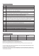
Record of Document Revisions: Revision 06/2004 04/2005 04/2005a 11/2005 12/2005 02/2006 05/2006 09/2006 03/2007 07/2007 10/2007 05/2008 06/2008 10/2008 02/2009 05/2010 07/2010 11/2010 12/2010 05/2011 09/2011 Remarks First edition Restart lock -AS-, UL-listing, new pinning for X8, several corrections order numbers 400V types for NA updated Chapter 1 updated, ComCoder wiring corrected, Acuro(BISS)-Interface new, max.
Kollmorgen 09/2011 Contents page 1 General About this manual . . . . . . . . . . . . . . . . . . . . . . . . . . . . . . . . . . . . . . . . . . . . . . . . . . . . . . . . . . . . . . . .7 Target group . . . . . . . . . . . . . . . . . . . . . . . . . . . . . . . . . . . . . . . . . . . . . . . . . . . . . . . . . . . . . . . . . . . .7 Hints for the online edition (PDF format) . . . . . . . . . . . . . . . . . . . . . . . . . . . . . . . . . . . . . . . . . . . . . .7 Abbreviations used . . . . . . .
Contents 09/2011 Kollmorgen page 6.10 Shock-hazard protection. . . . . . . . . . . . . . . . . . . . . . . . . . . . . . . . . . . . . . . . . . . . . . . . . . . . . . . . . .42 6.10.1 Leakage current . . . . . . . . . . . . . . . . . . . . . . . . . . . . . . . . . . . . . . . . . . . . . . . . . . . . . . . . . . .42 6.10.2 Residual current protective device (RCD). . . . . . . . . . . . . . . . . . . . . . . . . . . . . . . . . . . . . . . .42 6.10.3 Isolating transformers . . . . . . . . . . . . . .
Kollmorgen 09/2011 Contents page 8.16 Digital and analog inputs and outputs . . . . . . . . . . . . . . . . . . . . . . . . . . . . . . . . . . . . . . . . . . . . . . .87 8.16.1 Analog inputs (X3). . . . . . . . . . . . . . . . . . . . . . . . . . . . . . . . . . . . . . . . . . . . . . . . . . . . . . . . . .87 8.16.2 Digital inputs (X3/X4). . . . . . . . . . . . . . . . . . . . . . . . . . . . . . . . . . . . . . . . . . . . . . . . . . . . . . . .88 8.16.3 Digital outputs (X3) . . . . . . . . . . . .
Contents 09/2011 Kollmorgen page 10 Expansions Cards 10.1 Guide to installation of expansion cards. . . . . . . . . . . . . . . . . . . . . . . . . . . . . . . . . . . . . . . . . . . . .111 10.2 Expansion card -I/O-14/08- . . . . . . . . . . . . . . . . . . . . . . . . . . . . . . . . . . . . . . . . . . . . . . . . . . . . . .112 10.2.1 Technical data . . . . . . . . . . . . . . . . . . . . . . . . . . . . . . . . . . . . . . . . . . . . . . . . . . . . . . . . . . . .112 10.2.2 LEDs . . . . . . . . .
Kollmorgen 09/2011 1 General 1.1 About this manual General This manual describes the S300 series of digital servo amplifiers SERVOSTAR 300 (S300 standard version, 1.5A ...10A rated current).
General 1.4 Abbreviations used Abbrev.
Kollmorgen 1.5 09/2011 Symboles used Symbol 1.6 General Indication Indicates a hazardous situation which, if not avoided, will result in death or serious injury. Indicates a hazardous situation which, if not avoided, could result in death or serious injury. Indicates a hazardous situation which, if not avoided, could result in minor or moderate injury. Indicates situations which, if not avoided, could result in property damage. This is not a safety symbol. This symbol indicates important notes.
Safety 09/2011 2 Safety 2.1 Safety Instructions Kollmorgen During operation there are deadly hazards, with the possibility of death, severe injury or material damage. Do not open or touch the equipment during operation. Keep all covers and cabinet doors closed during operation. Touching the equipment is allowed during installation and commissioning for properly qualified persons only.
Kollmorgen 2.2 09/2011 Safety Use as directed Servo amplifiers are safety components that are built into electrical plant or machines, and can only be operated as integral components of such plant or machines. The manufacturer of the machine must generate a risk assessment for the machine, and take appropriate measures to ensure that unforeseen movements cannot cause injury or damage to any person or property.
Safety 2.3 09/2011 Kollmorgen Prohibited use Other use than described in chapter 2.2 is not intended and can lead to damage of persons, equipment or things. The use of the servo amplifier in the following environments is prohibited: potentially explosive areas environments with corrosive and/or electrically conductive acids, alkaline solutions, oils, vapors, dusts directly on non-grounded supply networks or on asymmetrically grounded supplies with a voltage >230V.
Kollmorgen 3 09/2011 Approvals Approvals Certificates can be found in our Product Wiki on page Approvals. 3.1 Conformance with UL and cUL This servo amplifier is listed under UL file number E217428. UL (cUL)-certified servo amplifiers (Underwriters Laboratories Inc.) fulfil the relevant U.S. and Canadian standard (in this case UL 840 and UL 508C).
Approvals 3.2 Kollmorgen 09/2011 EC Conformance Conformance with the EC Machine Directive 2006/42/EC, the EC EMC Directive 2004/108/EC and the Low Voltage Directive 2006/95/EC is mandatory for the supply of servo amplifiers within the European Community. The servo amplifier meets the noise immunity requirements to the 2nd environmental category (industrial environment). For noise emission the amplifier meets the requirement to a product of the category C2 (motor cable £ 10m).
Kollmorgen 3.2.
Approvals 3.3 Kollmorgen 09/2011 GOST-R conformance Certificate for servo amplifier and accessories (cover page, page 1 of 3).
Kollmorgen 09/2011 4 Handling 4.1 Transport 4.2 4.3 4.4 Handling l Transport by qualified personnel in the manufacturer’s original recyclable packaging l Avoid shocks while transporting l Transport temperature: -25 to +70°C, max. rate of change 20K / hour, class 2K3 acc. to EN61800-2 l Transport humidity: max. 95% relative humidity, no condensation, class 2K3 acc.
Handling 4.5 09/2011 Kollmorgen Disassembling Observe the sequence below, if a servo amplifier has to be disassembled (e.g. for replacement). 1. Electrical disconnection Switch off the main switch of the switchgear cabinet and the fuses that supply the system. Wait at least five minutes after disconnecting the servo amplifier from the main supply power before touching potentially live sections of the equipment (e.g. contacts) or undoing any connections.
Kollmorgen Package 09/2011 5 Package 5.1 Package supplied When an amplifier from the S300 series is ordered (order numbers ðp.129), the following is supplied: — — — — — — S3xx Mating connectors X0, X3, X4, X8 Mating connector X9 only with SERVOSTAR 303-310 (S3xx6) Instructions Manual Online documentation on CD-ROM Setup software DRIVEGUI.
Package 5.3 Kollmorgen 09/2011 Part number scheme S 3 0 6 0 1 - S E - zzz Family S3 S300 Customer specific specials Current rating 01 1.5A rms (208 to 480V only) 03 3A rms 06 6A rms 10 10A rms (110 to 230V only) Device Options NA Base device FN controlled FAN EC EtherCAT EF* FAN & EtherCAT Expansions NA no expansion, CANopen onboard DN DEVICENET PB PROFIBUS SE SERCOS SQ SYNQNET I/O I/O Extension Voltage rating 0 208...480V 6 110...230V Electr.
Kollmorgen 09/2011 6 Technical description 6.1 The S300 family of digital servo amplifiers Technical description Standard version l Two voltage classes with large nominal voltage range 1 x 110V-10% ... 3 x 230V+10% (SERVOSTAR 303-310, S3xx6) 3 x 208V-10% ... 3 x 480V+ 10% (SERVOSTAR 341-346, S3xx0) l Overvoltage category III acc.
Technical description Kollmorgen 09/2011 Auxiliary supply voltage 24V DC l Electrically isolated, internal fusing, from an external 24V DC power supply unit with, for instance, isolating transformer or uninterruptible power supply. Operation and parameter setting l With our user-friendly setup software, for setup via the serial interface of a PC. l If no PC is available: direct operation by two keys on the servo amplifier and a 3-character LED display. l Fully programmable via RS232 interface.
Kollmorgen Technical description 09/2011 6.2 Technical data 6.2.1 Technical data for 110/230 V (types S3_ _6_) Electrical data Order Code DIM — Rated supply voltage (grounded supply, phase to phase) V~ Rated input power for S1 operation kVA Permitted switch on/off frequency 1/h Max. DC bus link voltage V= Rated output current (rms value, ± 3%) at 1x115V (observe p. 58) Arms at 1x230V (observe p. 58) Arms at 3x115V Arms at 3x230V Arms Peak output current (current for approx.
Technical description 6.2.2 Technical data for 400/480 V (types S3_ _0_) Electrical data DIM Order Code — Rated supply voltage V~ (grounded supply, phase to phase) Rated input power for S1 operation kVA Permitted switch on/off frequency 1/h Max. DC bus link voltage V= Rated output current (rms value, ± 3%) at 3x208V Arms at 3x230V Arms at 3x400V Arms at 3x480V Arms Peak output current (max. approx.
Kollmorgen 6.2.3 09/2011 Inputs / outputs, Auxiliary voltage Interface Analog inputs 1, 2 (resolution 14/12 bit) Max. common-mode voltage Digital control inputs Digital control outputs, active high BTB/RTO output, relay contacts Auxiliary supply voltage, electrically isolated, without motor brake/fan Auxiliary supply voltage, electrically isolated, with motor brake/fan Min./max. output current to brake 6.2.4 Technical description electr. data ±10V ±10V as per IEC 61131-2 Type 1, max.
Technical description 6.2.7 Kollmorgen 09/2011 Ambient conditions, ventilation, mounting position Storage hints Transport hints Supply voltage ð p.17 ð p.17 303-310*: 341-346*: 1x110V-10% …1x230V+10%, 50/60 Hz 3x110V-10% …3x230V+10%, 50/60 Hz 3x208V-10% ...3x 480V+10%, 50/60 Hz Auxiliary voltage without brake and fan with brake or fan 20 V DC ... 30 V DC 24 V DC (-0% +15%), check voltage drop ! 0...+40°C under rated conditions Ambient temperature in operation +40...+55°C with power derating 2.
Kollmorgen 6.3 09/2011 Technical description Motor holding brake A 24V / max.1.5A holding brake in the motor can be controlled directly by the amplifier. This function does not ensure personnel safety! Hanging load (vertical axes) require an additional mechanical brake which must be safely operated. The brake only works with sufficient voltage level (ð p.25). Check voltage drop, measure the voltage at brake input and check brake function (brake and no brake).
Technical description 6.4 Kollmorgen 09/2011 LED display A 3-character LED display indicates the status of the amplifier after switching on the 24V supply (ð p.107). When the keys on the front panel are used, the parameter and function numbers are shown, as well as the numbers for any errors that may occur (ð p.108). 6.5 Grounding system AGND — analog inputs, internal analog ground, encoder emulation, RS232, CAN DGND — digital inputs/outputs and the 24V supply, optically isolated. 6.
Kollmorgen 09/2011 Technical description Technical Data: 343 / 346 (S30301/S30601) 341 (S30101) 306 / 310 (S30661/S31061) 303 (S30361) Brake circuit Type Rated data Switch-on (upper) threshold of brake circuit Overvoltage F02 Internal brake resistor (RBint) Continuous power for internal resistor (RBint) Max.
Technical description 6.7 09/2011 Kollmorgen Switch-on and switch-off behavior This chapter describes the switch-on and switch-off behavior of the S300 and the steps required to achieve operational stopping or emergency stop behavior that complies with standards. The servo amplifier’s 24 V supply must remain constant. The ASCII commands ACTFAULT (error response) and STOPMODE (ENABLE signal response) dictate how the drive will behave.
Kollmorgen 6.7.1 09/2011 Technical description Behavior in standard operation The behavior of the servo amplifier always depends on the current setting of a number of different parameters (e.g., ACTFAULT, VBUSMIN, VELO, STOPMODE, etc.; see online help). The diagram below illustrates the correct functional sequence for switching the servo amplifier on and off. Devices which are equipped with a selected “Brake” function use a special sequence for switching off the output stage (ð p.27).
Technical description 6.7.2 Kollmorgen 09/2011 Behavior in the event of an error (with standard setting) The behavior of the servo amplifier always depends on the current setting of a number of different parameters (e.g., ACTFAULT, VBUSMIN, VELO, STOPMODE, etc.; see online help). The diagram shows the startup procedure and the procedure that the internal control system follows in the event of one or more electrical supply phases failing, assuming that the standard parameter settings apply.
Kollmorgen 6.8 09/2011 Technical description Stop- / Emergency Stop- Function to IEC 60204 With the personnel safe, certified safety function STO (see page 35 onwards) the drive can be secured on standstill (torque-free) using its internal electronics so that even when power is being supplied, the drive shaft is protected against unintentional restart. The parameters “STOPMODE” and “ACTFAULT” must be set to 1 in order to implement the stop categories.
Technical description 6.8.2 09/2011 Kollmorgen Emergency Stop: Standards The emergency Stop function is used for the fastest possible shut-down of the machine in a dangerous situation. The Emergency Stop function can be triggered by the actions of a single person. It must be fully functional and available at all times. The user must not have to work out how to operate this mechanism. The Emergency Stop function is defined by IEC 60204.
Kollmorgen 6.9 Technical description 09/2011 Safety function STO A frequently required application task is the protection of personnel against the restarting of drives. The S300 servo amplifier offers, even in the basic version, a single channel STO function (Safe Torque Off) that can be used as a personnel safe restart lock. The safety function STO can be operated from a safe external control (semiconductor output or driven contact). The safetys concept is certified.
Technical description 6.9.2 09/2011 Kollmorgen Safety instructions Drives with a suspended load must have an additional safe mechanical blocking (e.g. by a motor-holding brake). The amplifier cannot hold the load when STO is active. That could result in serious injury. When STO is engaged during operation by separating input STO-Enable from 24VDC, the motor runs down out of control and the servo amplifier displays the error F27. There is no possibility of braking the drive controlled.
Kollmorgen 6.9.5 09/2011 Technical data and pinning Input voltage Input current Peak current 6.9.6 Technical description 20 V..30 V 33 mA – 40 mA (Ieff) 100 mA (Is) Enlosure Since the servo amplifier meets enclosure IP20, you must select the environment ensuring a safe operation of the servo amplifier. The enclosure must meet IP54 at least. 6.9.7 Wiring When using STO wiring leads outside the control cabinet, the cables must be laid durably (firmly), protected from outside damage (e.g.
Technical description 6.9.8 Kollmorgen 09/2011 Functional description In case of use of the STO function the input STO-Enable must be connected to the exit of a security control or a safety relay, which meets at least to therequirements of the SIL CL2 according to IEC 62061 and PL d according to ISO 13849-1 (see the connection diagram on page 40).
Kollmorgen 6.9.8.1 09/2011 Technical description Signal diagram (sequence) The diagram shows how to use STO function to ensure a safe stop of the drive and error free operation of the servo amplifier. 1. 2. 3.
Technical description 6.9.8.2 09/2011 Kollmorgen Control circuit The example shows a circuit diagram with two separated work areas connected to one emergency stop circuit. For each work area individually "safe stop" of the drives is switched by a protective screen. The safety switch gears used in the example are manufactured by Pilz and fulfill at least the PL d acc. to ISO 13849-1. Further information to the safety switch gears is available from Pilz.
Kollmorgen 6.9.8.3 09/2011 Technical description Functional test With initial starting and after each interference into the wiring of the drive or after exchange of one or several components of the drive the STO function must be tested. 1. Method: 1. Stop drive, with setpoint 0V, keep servo amplifier enabled. DANGER: Do not enter hazardous area! 2. Activate STO e.g. by opening protective screen.
Technical description Kollmorgen 09/2011 6.10 Shock-hazard protection 6.10.1 Leakage current Leakage current via the PE conductor results from the combination of equipment and cable leakage currents. The leakage current frequency pattern comprises a number of frequencies, whereby the residual-current circuit breakers definitively evaluate the 50Hz current.
Kollmorgen 09/2011 7 Mechanical Installation 7.1 Safety Instructions Mechanical Installation There is a danger of electrical shock by high EMC level which could result in injury, if the servo amplifier (or the motor) isn't properly EMC-grounded. Do not use painted (i.e. non-conductive) mounting plates. Protect the servo amplifier from impermissible stresses. In particular, do not let any components become bent or any insulation distances altered during transport and handling.
Mechanical Installation 7.
Kollmorgen 7.4 09/2011 Mechanical Installation Dimensions 1 xx6 S3 x01 x S3 0 .31 3.. 6 0 3 .34 1..
Mechanical Installation Kollmorgen 09/2011 This page has been deliberately left blank.
Kollmorgen 09/2011 8 Electrical installation 8.1 Safety Instructions Electrical installation Never undo any electrical connections to the servo amplifier while it is live. There is a danger of electrical arcing with damage to contacts and serious personal injury. Wait at least five minutes after disconnecting the servo amplifier from the main supply power before touching potentially live sections of the equipment (e.g. contacts) or undoing any connections.
Electrical installation 8.2 Kollmorgen 09/2011 Guide to electrical installation The following notes should help you to carry out the electrical installation. Cable selection Select cables in accordance with IEC 60204 ð p.26. Grounding Shielding Wiring Final check 48 For EMC-compliant shielding and grounding ð p.55. Ground the mounting plate, motor housing and CNC-GND of the control system. Notes on connection techniques ð p.50. Route power leads and control cables separately.
Kollmorgen 8.3 Electrical installation 09/2011 Wiring The installation procedure is described as an example. A different procedure may be appropriate or necessary, depending on the application of the equipments. We provide further know-how through training courses (on request). 8.3.1 Safety instructions There is a danger of electrical arcing with serious personal injury. Only install and wire up the equipment when it is not live, i.e.
Electrical installation 8.3.2 09/2011 Kollmorgen Shielding connection to the front panel Remove the outside shroud of the cable and the shielding braid on the desired core length. Secure the cores with a cable tie. Remove the outside shroud of the line on a length from for instance 30mm without damaging the shielding braid. Pull a cable tie by the slot in the shielding rail on the front panel of the servo amplifier. Press the shielding of the cable firmly against the front panel with the cable tie.
Kollmorgen 8.3.3 09/2011 Electrical installation Technical data for connecting cables Further information on the chemical, mechanical and electrical characteristics of the cables can be obtained from our customer service. Observe the rules in the section "Conductor cross-sections" on page 26. To reach the max. permitted cable length, you must use cable material that matches the capacitance requirements listed below.
Electrical installation 8.4 Kollmorgen 09/2011 Components of a servo system PC Controls / PLC S300 24V PSU Fuses Brake resistor (optional) Drive cut-out Motor choke (optional) Terminals Motor Cables drawn bold are shielded. Electrical ground is drawn with dash-dotted lines. Optional devices are connected with dashed lines to the servo amplifier. The required accessories are described in our accessories manual.
Kollmorgen 8.5 09/2011 Electrical installation Block diagram The block diagram below just provides an overview.
Electrical installation 8.6 09/2011 Kollmorgen Connector assignments The connectors of the expansion card depend on used expansion card (see pages 112 ff).
Kollmorgen 8.7 09/2011 Electrical installation Connection diagram (Overview) Refer to the Safety Instructions (ðp.10) and Use as Directed (ð p.11) ! S300 ð p.64ff ð p.87 ð p.63 ð p.88 ð p.60 ð p.59 ð p.57 ð p.89 ð p.88 ð p.37 ð p.85 ð p.86 ð p.81 ð p.82 ð p.91 ð p.57 ð p.90 ð p.112 ð p.115 ð p.116 ð p.118 ð p.125 ð p.
Electrical installation Kollmorgen 09/2011 8.8 Electrical supply 8.8.1 Connection to various mains supply networks There is a danger of electrical shock with serious personal injury if the servo amplifier isn't properly grounded. An isolating transformer is always required for 400 … 480V networks that are asymmetrically grounded or not grounded.
Kollmorgen 8.8.2 09/2011 Electrical installation 24V auxiliary supply (X4) — External 24V DC power supply, electrically isolated, e.g. via an isolating transformer — Required current rating ð p.23 — Integrated EMC filter for the 24V auxiliary supply S300 8.8.3 Mains supply connection (X0), three phase — — Directly to 3-phase supply network, filter is integrated Fusing (e.g. fusible cut-outs) to be provided by the user ð p.25 S300 8.8.
Electrical installation 8.8.5 Kollmorgen 09/2011 Mains supply connection (X0), single phase with neutral S300 with 230V version (SERVOSTAR 303-310) can be operated with a single phase mains supply. In single phase operation the electrical power of the amplifier is limited. The table below shows the maximum rated power (Pn) and peak power (Pp) with single phase operation: S300 max.
Kollmorgen 8.9 09/2011 Electrical installation External brake resistor (X8) Remove the plug-in link between the terminals X8/5 (-RB) and X8/4 (+Rbint). S300 8.10 DC bus link (X8) Terminals X8/1 (-DC) and X8/3 (+RBext). Can be connected in parallel, whereby the brake power is divided between all the amplifiers that are connected to the same DC bus link circuit. S300 S300 The servo amplifiers can be destroyed, if DC bus link voltages are different.
Electrical installation 8.11 09/2011 Kollmorgen Motor connection with brake (X9) Together with the motor supply cable and motor winding, the power output of the servo amplifier forms an oscillating circuit. Characteristics such as cable capacity, cable length, motor inductance, frequency and voltage rise speed (see Technical Data, p. 23) determine the maximum voltage in the system.
Kollmorgen 8.12 Electrical installation 09/2011 Feedback systems Every closed servo system will normally require at least one feedback device for sending actual values from the motor to the servo drive. Depending on the type of feedback device used, information will be fed back to the servo amplifier using digital or analog means. Up to three feedback devices can be used at the same time.
Electrical installation 8.13 Kollmorgen 09/2011 Primary and secondary feedback types The table below provides an overview of the supported feedback types, their corresponding parameters and a reference to the relevant connection diagram in each case. FBTYPE EXTPOS set on DRIVEGUI.EXE screen page FEEDBACK, primary Feedback set on DRIVEGUI.EXE screen page POSITION CONTROLLER, secondary Feedback For a detailed description of the ASCII parameters, please refer to the online help of the setup software.
Kollmorgen 8.13.1 09/2011 Electrical installation Resolver (X2) Connection of a Resolver (2 to 36-poles) as a feedback system (primary, ð p.62). The thermal control in the motor is connected via the resolver cable to X2 and evaluated there. If cable lengths of more than 100m are planned, please consult our customer service. FBTYPE: 0 S300 SubD 9 round 12-pin The pin assignment shown on the encoder side relates to the Kollmorgen motors.
Electrical installation 8.13.2 Kollmorgen 09/2011 Sine Encoder with BiSS analog (X1) Wiring of a single-turn or multi-turn sine-cosine encoder with BISS interface as a feedback system (primary and secondary, ð p.62). The thermal control in the motor is connected via the encoder cable to X1 and evaluated there. If cable lengths of more than 50m are planned, please consult our customer service.
Kollmorgen 8.13.3 Electrical installation 09/2011 Sine Encoder with BiSS digital (X1) Wiring of a single-turn or multi-turn digital encoder with BISS interface as a feedback system (primary and secondary, ð p.62). The thermal control in the motor is connected via the encoder cable to X1 and evaluated there. If cable lengths of more than 50m are planned, please consult our customer service.
Electrical installation 8.13.4 Kollmorgen 09/2011 Sine Encoder with EnDat 2.1 (X1) Wiring of a single-turn or multi-turn sine-cosine encoder with EnDat 2.1 interface as a feedback system (primary and secondary, ð p.62). Preferred types are the optical encoder ECN1313 / EQN1325 and the inductive encoder ECI 1118/1319 or EQI 1130/1331. The thermal control in the motor is connected via the encoder cable to X1 and evaluated there. All signals are connected using our pre-assembled encoder connection cable.
Kollmorgen 8.13.5 09/2011 Electrical installation Sine Encoder with EnDat 2.2 (X1) Wiring of a single-turn or multi-turn sine-cosine encoder with EnDat 2.2 interface as a feedback system (primary, ð p.62). The thermal control in the motor is connected via the encoder cable to X1 and evaluated there. All signals are connected using our pre-assembled encoder connection cable. If cable lengths of more than 50m are planned, please consult our customer service. Frequency limit: 1.5 MHz Type ENDAT 2.
Electrical installation 8.13.6 Kollmorgen 09/2011 Sine Encoder with HIPERFACE (X1) Wiring of a single-turn or multi-turn sine-cosine encoder with HIPERFACE interface as a feedback system (primary and secondary, ð p.62). The thermal control in the motor is connected via the encoder cable to X1 and evaluated there. All signals are connected using our pre-assembled encoder connection cable. If cable lengths of more than 50m are planned, please consult our customer service.
Kollmorgen 8.13.7 09/2011 Electrical installation Sine Encoder with SSI (X5, X1) Wiring of sine-cosine encoder with SSI interface as a linear feedback system (primary, ð p.62) to X5. The thermal control in the motor is connected via the encoder cable to X1 and evaluated there. All signals are connected using our pre-assembled encoder connection cable. If cable lengths of more than 50m are planned, please consult our customer service.
Electrical installation 8.13.8 09/2011 Kollmorgen Sine Encoder without data channel (X1) Wiring of a sine-cosine encoder without data channel as a feedback (primary and secondary, ð p.62). The thermal control in the motor is connected via the encoder cable to X1 and evaluated there. Every time the 24V auxiliary voltage is switched on, the amplifier needs start-up information for the position controller (parameter value MPHASE).
Kollmorgen 8.13.9 Electrical installation 09/2011 Sine Encoder with Hall (X1) Feedback devices (incremental or sine-cosine), which don't deliver an absolute information for commutation, can be used as complete feedback system combined with an additional Hall encoder (primary, ð p.62). All signals are connected to X1 and evaluated there. If cable lengths of more than 25m are planned, please consult our customer service.
Electrical installation 8.13.10 Kollmorgen 09/2011 ROD (AquadB) 5V, 1.5 MHz (X1) Wiring of a 5V incremental encoder (ROD, AquadB) as a feedback (primary or secondary, ð p.62). Every time the 24V auxiliary voltage is switched on, the amplifier need start-up information for the position controller (parameter value MPHASE). Depending on the setting of FBTYPE a wake&shake is executed or the value for MPHASE is taken out of the servo amplifier's EEPROM.
Kollmorgen 8.13.11 09/2011 Electrical installation ROD (AquadB) 5V, 350 kHz (X1) Wiring of a 5V incremental encoder (ROD, AquadB) as a feedback ((primary or secondary, ð p.62). The thermal control in the motor is connected to X1 and evaluated there. Every time the 24V auxiliary voltage is switched on, the amplifier need start-up information for the position controller (parameter value MPHASE). With this feedback type the amplifier executes a wake&shake every time the 24V auxiliary voltage is switched on.
Electrical installation 8.13.12 Kollmorgen 09/2011 ROD (AquadB) 5V with Hall (X1) Wiring of a ComCoder as a feedback unit (primary, ð p.62). For the commutation hall sensors are used and for the resolution an incremental encoder. The thermal control in the motor is connected to X1 and evaluated there. With our ComCoder cable all signals are connected correctly.With separate feedback devices (Encoder and Hall are two devices) the wiring must be done similar to chapter 8.13.
Kollmorgen 8.13.13 09/2011 Electrical installation ROD (AquadB) 5V (X5) A 5V incremental encoder (AquadB) can be used as standard motor feedback (primary and secondary, ð p.62). The thermal control in the motor is connected to X1. Every time the 24V auxiliary voltage is switched on, the amplifier need start-up information for the position controller (parameter value MPHASE). Depending on the feedback type either wake&shake is executed or the value for MPHASE is read out of the amplifier's EEPROM.
Electrical installation 8.13.14 Kollmorgen 09/2011 ROD (AquadB) 5V with Hall (X5, X1) Wiring of a 5V incremental encoder (ROD, AquadB) with Hall sensors as a feedback unit (primary, ð p.62). For the commutation hall sensors are used and for the resolution an incremental encoder. The thermal control in the motor is connected to X1 and evaluated there. If cable lengths of more than 25m are planned, please consult our customer service. Frequency limit X5: 1.
Kollmorgen 8.13.15 09/2011 Electrical installation ROD (AquadB) 24V (X3) Wiring of a 24V incremental encoder (ROD AquadB) as a feedback system (primary or secondary, ð p.62). The thermal control in the motor is connected to X1 or X2. Every time the 24V auxiliary voltage is switched on, the amplifier need start-up information for the position controller (parameter value MPHASE). With this feedback type the amplifier executes a wake&shake is executed every time the 24V auxiliary voltage is switched on.
Electrical installation 8.13.16 Kollmorgen 09/2011 ROD (AquadB) 24V with Hall (X3, X1) Wiring of a 24V incremental encoder (ROD, AquadB) and Hall sensors as a feedback unit (primary, ð p.62). For the commutation hall sensors are used and for the resolution an incremental encoder. The thermal control in the motor is connected to X1 and evaluated there. If cable lengths of more than 25m are planned, please consult our customer service.
Kollmorgen 8.13.17 09/2011 Electrical installation SSI Encoder (X5, X1) Wiring of a synchronous serial absolute encoder as a feedback system (primary or secondary, ð p.62). The signal sequence can be read in Gray code or in Binary (standard) code. The thermal control in the motor is connected to X1 and evaluated there. If cable lengths of more than 50m are planned, please consult our customer service. Frequency limit: 1.
Electrical installation 8.13.18 Kollmorgen 09/2011 Hall sensors (X1) Wiring of Hall sensors as a feedback unit (primary, ð p.62). The thermal control in the motor is connected to X1 and evaluated there. If cable lengths of more than 25m are planned, please consult our customer service.
Kollmorgen 8.14 Electrical installation 09/2011 Electronic Gearing, Master-slave operation In the case of the “electronic gearing” functionality (see setup software and description of GEARMODE parameter), the servo amplifier is controlled by a secondary feedback device as a slave. It is possible to set up master/slave systems, use an external encoder as a setpoint encoder or connect the amplifier to a stepper motor control. The amplifier is parameterized using the setup software (electronic gearing).
Electrical installation 8.14.2 Kollmorgen 09/2011 Connection to stepper motor controllers (step and direction) You can connect the servo amplifier to a third-party stepper-motor controller. Parameter setting for the slave amplifier is carried out with the aid of the setup software (electronic gearing). The number of steps can be adjusted, so that the servo amplifier can be adapted to match the step-direction signals of any stepper controller. Various monitoring signals can be generated.
Kollmorgen 8.14.2.3 09/2011 Electrical installation Step/Direction 5V, 1.5 MHz (X5) Wiring of the servo amplifier (SubD connector X5) to a stepper-motor controller with a 5 V signal level. Frequency limit: 1.
Electrical installation 8.14.3 Kollmorgen 09/2011 Master-Slave Connection You can, for example, link several S300 amplifiers together in master-slave operation. Up to 16 slave amplifiers can be controlled by the master, via the encoder output. 8.14.3.1 Master Slave 5V (X1) Functionality not available. 8.14.3.2 Master Slave 5V (X5) Master: Slave: position output to X5 (screen page "Encoder emulation") screen page "Electronic gearing" (GEARMODE) Frequency limit X5: 1.
Kollmorgen Electrical installation 09/2011 8.15 Encoder emulation 8.15.1 Incremental encoder output - A quad B (X5) The incremental-encoder interface is part of the standard package. Select encoder function ROD (A Quad B) Encoder (“Encoder Emulation” screen page). The servo amplifier calculates the motor shaft position from the cyclic- absolute signals of the resolver or encoder, generating incremental-encoder compatible pulses from this information.
Electrical installation 8.15.2 Kollmorgen 09/2011 SSI encoder output (X5) The SSI interface (synchronous serial absolute-encoder emulation) is part of the standard package. Select encoder function SSI (“Encoder Emulation” screen page, ENCMODE 2). The servo amplifier calculates the motor shaft position from the cyclic-absolute signals of the resolver or encoder. From this information a SSI date (Stegmann patent specification DE 3445617C2) is provided. Max 32 bits are transferred.
Kollmorgen 09/2011 8.16 Digital and analog inputs and outputs 8.16.1 Analog inputs (X3) Electrical installation The servo amplifier is fitted with two programmable differential inputs for analog setpoints. AGND (X3/7) must always be joined to the GND of the controls as a ground reference. Technical characteristics — — — — — Differential-input voltage max. ± 10 V Ground reference AGND, terminal X3/7 Input resistance 2.
Electrical installation 8.16.2 Kollmorgen 09/2011 Digital inputs (X3/X4) All digital inputs are electrically isolated via optocouplers. Technical characteristics — — — Ground reference is Digital-GND (DGND, terminals X4/3 and X4/4) The inputs at X3 are PLC-compatible (IEC 61131-2 Type 1) High: 11...30 V / 2...11 mA , Low: -3...
Kollmorgen 8.16.3 09/2011 Electrical installation Digital outputs (X3) Technical characteristics — — — — Ground reference is Digital-GND (DGND, terminals X4/3 and X4/4) All digital outputs are floating DIGITAL-OUT1 and 2 : Open Emitter, max. 30 V DC, 10 mA BTB/RTO : Relay output, max. 30 V DC or 42 V AC, 0.5 A Update rate 250 µs S300 Ready-to-operate contact BTB/RTO Operational readiness (terminals X3/1 and X3/2 ) is signaled by a floating relay contact.
Electrical installation 8.17 Kollmorgen 09/2011 RS232 interface, PC connection (X6) Operating, position control, and motion-block parameters can be set up by using the setup software on an ordinary commercial PC. Connect the PC interface (X6) of the servo amplifier to a serial interface on the PC via a null-modem cable, while the supply to the equipment is switched off. Do not use a null-modem power link cable! This interface has the same electrical potential as the CANopen interface.
Kollmorgen 8.18 09/2011 Electrical installation CANopen interface (X6) The interface for connection to the CAN-bus (default : 500 kBaud). The integrated profile is based on the CANopen DS301 communication profile and the DS402 drive profile. The following functions are available in connection with the position controller: Jogging with variable speed, homing run (zeroing to reference), start motion task, start direct task, digital setpoint provision, data transmission functions and many others.
Electrical installation Kollmorgen 09/2011 This page has been deliberately left blank.
Kollmorgen 9 09/2011 Setup Setup The procedure for setup is described as an example. Depending on the application, a different procedure may be appropriate or necessary. In multi-axis systems, set up each servo amplifier individually. 9.1 Safety Instructions The equipment produces potentially lethal voltages up to 900 V. Check that all connection components that are live in operation are safely protected against bodily contact.
Setup Kollmorgen 09/2011 9.2 Setup software 9.2.1 General This chapter describes the installation of the setup software DRIVEGUI.EXE for the S300 digital servo amplifiers. We offer training and familiarization courses on request. 9.2.1.1 Use as directed The setup software is intended to be used for altering and saving the operating parameters for the S300 series of servo amplifiers.
Kollmorgen 9.2.1.3 09/2011 Setup Hardware requirements The PC interface (X6, RS232) of the servo amplifier is connected to the serial interface of the PC by a null-modem cable (not a null-modem link cable!) (ð p.90). Connect / disconnect the interface cable only when the electrical supply is switched off for both the PC and the servo amplifier. The interface in the servo amplifier has the same potential level as the CANopen interface. Minimum requirements for the PC: 9.2.1.
Setup Kollmorgen 09/2011 9.3 Quickstart 9.3.1 Preparation 9.3.1.1 Unpacking, Mounting and Wiring the Servo Amplifier 1. Unpack servo amplifier and accessories 2. Observe safety instructions in the manuals 3. Mount the servo amplifier as described in chapter 7 4. Wire the servo amplifier as described in chapter 8 or apply the minimum wiring for drive testing as described in chapter 9.3.1.3 5. Install the software as described in chapter 9.2 9.3.1.
Kollmorgen 9.3.1.3 Setup 09/2011 Minimum Wiring for Drive Test This wiring does not fulfill any requirements to safety or functionality of your application, it just shows the required wiring for drive testing without load.
Setup 9.3.2 Kollmorgen 09/2011 Connect l Connect the interface cable to a serial interface on your PC and to the serial interface X6 of the servo amplifier. USB to serial converter can be used optionally. l Switch on the 24 V power supply for the servo amplifier. l Wait about 30 seconds, until the front display of the servo amplifier displays the current class (e.g. for 3 A). If the power supply voltage is switched on, too, a lea- ding P is displayed (e.g. for Power, 3 A).
Kollmorgen 09/2011 Setup If communication works, you see the start screen. Select "Setup Wizard" in the navigation frame. Make sure, that the amplifier is disabled (Input Enable connector X3 pin 12 must be 0 V or open)! 9.3.3 Important Screen Elements Help Function The online help gives detailed information to all parameters the servo amplifier can work with. Key F1 Menu bar Help Starts online help for the actual screen page. Starts online help with the first page. Context Help.
Setup 9.3.4 09/2011 Kollmorgen Setup Wizard The Setup Wizard leads you through the necessary steps for configuring your servo amplifier. Depending on the selected application, only the active screen pages are necessary. For a quick setup / drive test, select the setup type "Quick Motor/Drive Setup". Start the Wizard. 9.3.4.1 Basic Setup Basic parameters are setup here. Response to Loss of Input Phase: Select Single-Phase or Three-Phase operation.
Kollmorgen 9.3.4.2 09/2011 Setup Units/Mechanical The user units for all input fields in the setup software can be preselected here. Position, Velocity, Acceleration Select usable units for your application referring to the moved load. Mechanical Conversion The relationship between motor shaft revolution (pole pait pitch with linear motors) and motion distance of the load is specified here. Gear ratio can be calculated here as well. Detailed information can be found in the online help.
Setup 9.3.4.3 09/2011 Kollmorgen Motor (rotary) / Feedback Simplified setting of the motor related parameters. Feedback: Select the feedback system used in the motor. Attention: Resolver is fixed to 2 pole in the Quick Motor/Drive Setup. Change "pole n°" on feedback screen in Complete Setup later, if required. Motor type: Click the button "Select from Database...". Open the database file (mdb_ _ _.csv) and select the used motor out of the list. Special motors must be defined in the "Complete Setup".
Kollmorgen 9.3.4.5 Setup 09/2011 Save Parameters and Restart You are going to finish the Setup Wizard and you have changed several basic parameters. Depending on the parameters you changed, two possible reactions will occure now: Configuration parameters changed A warning appears, that you have to restart the amplifier, this is called "coldstart". Click "YES". The parameters are saved to the amplifier's EEPROM automatically and a reset command restarts the amplifier (takes some seconds).
Setup 9.3.6 Kollmorgen 09/2011 More Setup Screens Observe the safety instructions in the manuals and in the online help before you change parameters in the additional setup screens. For all setup functions detailed information can be found in the online help system and the integrated command reference. Select "Complete Setup" in the Setup-Wizard.
Kollmorgen 9.4 Setup 09/2011 Multi-axis system With a special cable you can connect up to 255 servo amplifiers to your PC: cable type -SR6Y- (for four aplifiers) or -SR6Y6- (for six amplifiers) see Accessories Manual. Addr.: 00 Cable -SR6Y- COMx RS232 Addr.: 01 Addr.: 02 Addr.: 03 Baudrate identical for all amplifiers, see table below With the PC connected to only one amplifiers you can select every amplifier in the system via the set station address with the setup software. 9.4.
Setup 9.5.1 Kollmorgen 09/2011 Keypad operation The two keys can be used to perform the following functions: Key symbol Functions press once : move up one menu item, increase number by one press twice in rapid succession : increase number by ten press once : decrease number by one press twice in rapid succession : decrease number by ten hold right key pressed, and then press left key as well : to enter a number, “Return” function 9.5.2 Status display ð p.105 9.5.
Kollmorgen 9.5.4 Setup 09/2011 Advanced menu To operate the amplifier via the advanced menu, you must keep the right key pressed while switching on the 24 V supply. ð p.105 ð p.
Setup 9.6 09/2011 Kollmorgen Error messages Any errors that occur are shown in coded form by an error number in the LED display on the front panel. All error messages result in the BTB/RTO contact being opened, the output stage being switched off (motor loses all torque), and the holding brake is activated. Number E/P ... -SF01 Explanation Status Messages Status Message Status Message STO-Enable Heat Sink Temperature Status messages, no error, see p.
Kollmorgen 9.7 09/2011 Setup Warning messages Faults which occur, but which do not cause a switch-off of the amplifier output stage (BTB/RTO contact remains closed), are indicated in the LED display on the front panel by a coded warning number. Number E/P ...
Setup 9.8 Kollmorgen 09/2011 Trouble Shooting There may be a wide variety of reasons for the fault, depending on the conditions in your installation. In multi-axis systems there may be further hidden causes of a fault. Detailled hints for removal of faults can be found in the online help chapter "Trouble-Shooting". Our customer service can give you further assistance with problems.
Kollmorgen 10 09/2011 Expansions Cards Expansions Cards You can find information about availability and order numbers on page 129. Expansions cards can only be built into amplifiers without option FAN! 10.1 Guide to installation of expansion cards l Use a suitable screwdriver to lever off the cover of the option slot. l Take care that no small items (such as screws) fall into the open option slot. l Lever off the small metall sheet and push it back to the small slot. Dispose the big metall sheet.
Expansions Cards 10.2 Kollmorgen 09/2011 Expansion card -I/O-14/08This section describes the additional features that the expansion card -I/O-14/08- provides for the S300. If you ordered the expansion card together with the servo amplifier, then it will be delivered already inserted into the expansion slot of the servo amplifier and screwed in place. The -I/O-14/08- provides you with 14 additional digital inputs and 8 digital outputs.
Kollmorgen 10.2.4 09/2011 Expansions Cards Connector assignments The functions are adjustable with the setup software. In the table below the default values are described. Connector X11A Default Pin Dir Description function 1 In A0 Motion block number, LSB 2 In A1 Motion block number, 21 3 In A2 Motion block number, 22 4 In A3 Motion block number, 23 5 In A4 Motion block number, 24 6 In A5 Motion block number, 25 7 In A6 Motion block number, 26 8 In A7 Motion block number, MSB Polls the home switch.
Expansions Cards 10.2.
Kollmorgen 10.3 09/2011 Expansions Cards Expansion card -PROFIBUSThis section describes the PROFIBUS expansion card for the S300. Information on the range of functions and the software protocol can be found in our manual “Communication Profile PROFIBUS DP”.. The PROFIBUS expansion card has two 9-pin SubD sockets wired in parallel. The supply voltage for the expansion card is provided by the servo amplifier. 10.3.
Expansions Cards 10.4 09/2011 Kollmorgen Expansion card -SERCOSThis section describes the SERCOS expansion card for S300. Information on the range of functions and the software protocol can be found in our manual “Communication Profile SERCOS”. 10.4.1 LEDs RT TT Indicates whether SERCOS telegrams are being correctly received. In the final Communication Phase 4 this LED should flicker, since cyclical telegrams are being received. Indicates that SERCOS telegrams are being transmitted.
Kollmorgen 10.4.3 09/2011 Expansions Cards Connection diagram Layout of the SERCOS bus system in ring topology, with optical fiber cables (schematic). 10.4.4 Modifying the station address The drive address can be set to a value between 0 and 63. With address 0, the drive is assigned as an amplifier in the SERCOS ring. Set the station address with the: Keys on the front of the servo amplifier The SERCOS address can be modified using the keys on the front of the amplifier (p. 106).
Expansions Cards 10.5 09/2011 Kollmorgen Expansion card -DEVICENETThis section describes the DeviceNet expansion card for S300. Information on the range of functions and the software protocol can be found in our manual “DeviceNet Communication Profile”. 10.5.1 Connection technology Cable selection, cable routing, shielding, bus connector, bus termination and transmission times are all described in the “DeviceNet Specification, Volume I, II, Edition 2.0”, published by ODVA. 10.5.
Kollmorgen 10.5.3 09/2011 Expansions Cards Combined module/network status-LED LED Meaning The device is not online. - The device has not yet finished the Dup_MAC_ID test. off - The device is possibly not yet switched on. The device is operating as normal, is online, and the connections have been green established. The device has been assigned to a master. The device is operating as normal, is online, but the connections have not been established.
Expansions Cards 10.5.6 09/2011 Kollmorgen Bus cable To meet ISO 11898, a bus cable with a characteristic impedance of 120 W should be used. The maximum usable cable length for reliable communication decreases with increasing transmission speed. As a guide, you can use the following values which we have measured, but they are not to be taken as assured limits.
Kollmorgen 10.6 Expansions Cards 09/2011 Expansion card -SYNQNETThis section describes the SynqNet expansion card for S300. Information on the range of functions and the software protocol can be found in the SynqNet documentation. 10.6.1 NODE ID Switch LED2 LED1 LED4 LED3 With these hexadecimal switches you can set the main and low significant bytes of the Node ID seperately.
Expansions Cards 10.6.4 Kollmorgen 09/2011 Digital inputs/outputs, connector X21A (SubD 15-pin, socket) Inputs (In): 24V (20...28V), opto-isolated, one high-speed input (Pin 4) Outputs (Out): 24V, opto-isolated, Darlington driver Pinout connector X21A (SubD 15 pin) Pin Type Description In +24V power supply 1 NODE- indicates a problem Out 2 ALARM with the node Out OUT_01 digital output 3 In IN_00 capture input (fast) 4 In IN_04 digital input 5 10.6.
Kollmorgen 10.7 09/2011 Expansions Cards Expansion module -2CANConnector X6 of the S300 is assigned to the signals for the RS232 interface and the CAN interface. It is therefore not the standard pin assignment for these interfaces, and a special cable is required to be able to use both interfaces simultaneously. The -2CAN- expansion module provides the interfaces on separate Sub-D connectors. The two CAN connectors are wired in parallel.
Expansions Cards 10.7.3 Connector assignments RS232 X6A Pin 1 2 3 4 5 6 7 8 9 10.7.
Kollmorgen 10.8 Expansions Cards 09/2011 Option "EtherCAT" Offers EtherCAT interface to the S300. This option uses the expansion slot. Information on the range of functions and the software protocol can be found in the EtherCAT documentation. This option enables the S300 to be connected to the EtherCAT network via RJ-45 connectors (IN and OUT ports). The option EtherCAT cannot be inserted later. Order the amplifier with built-in EtherCAT option. LED3 LED4 10.8.
Expansions Cards 10.9 Kollmorgen 09/2011 Option "FAN", ventilator control To reduce the average noise emission of servo amplifiers with fan, these amplifiers can be ordered with built-in fan option card (ventilator control). This option uses (invisible from the outside) the expansion slot. The option FAN cannot be inserted later. Order the amplifier with built-in FAN option. Function The fan is switched on and off depending on measured temperature values and brake power.
Kollmorgen 09/2011 Appendix 11 Appendix 11.1 Glossary B Brake circuit Converts superfluous energy fed back by the motor during braking (regenerated energy) into heat.
Appendix M Kollmorgen 09/2011 Machine The complete assembly of all connected parts or devices, of which at least one is movable Motion block Data packet with all the position control parameters which are required for a motion task Multi-axis system Machine with several independently driven axes N Natural convection Free movement of air for cooling O Optocoupler Optical connection between two electrically independent systems P P-controller Control loop with purely proportional behavior Phas
Kollmorgen 11.2 Appendix 09/2011 Order codes The order numbers of accessories such as cables, brake resistors, mains supplies, etc., can be found in the accessories manual. 11.2.
Appendix 11.
Kollmorgen 11.4 09/2011 Index ! 24V aux. supply, interface . . . . . . . 57 A Abbreviations . . . . . . . . . . . . . . . 8 Ambient temperature . . . . . . . . . . 26 Assembly . . . . . . . . . . . . . . . . 44 Baud rate . . . . . . . . . . . . . . . 105 BiSS interface analog . . . . . . . . . . 64 BiSS interface digital . . . . . . . . . . 65 Block diagram (overview) . . . . . . . . 53 Brake resistor Interface, ext. . . . . . . . . . . . . 59 Technical data . . . . . . . . . . . .
Appendix S T U V W 132 09/2011 Kollmorgen Safety characteristic data . . . . . . . . 35 Safety Function STO . . . . . . . . . . 35 Safety instructions. . . . . . . . . . . . 10 Setup . . . . . . . . . . . . . . . . . . 93 Shielding Connection diagram,. . . . . . . . . 55 Installation . . . . . . . . . . . . . . 48 Shock-hazard protection . . . . . . . . 42 SinCos+SSI to X5 . . . . . . . . . . . . 69 Site . . . . . . . . . . . . . . . . . . . 43 Site altitude . . . . . . . . . . . . . . .
Kollmorgen 09/2011 Appendix This page has been deliberately left blank.
Service We are committed to quality customer service. In order to serve in the most effective way, please contact your local sales representative for assistance. If you are unaware of your local sales representative, please contact the Customer Support. Europa Kollmorgen Customer Support Europe Internet www.kollmorgen.com E-Mail technik@kollmorgen.com Tel.: +49 (0)2102 - 9394 - 0 Fax: +49 (0)2102 - 9394 - 3155 North America Kollmorgen Customer Support North America Internet www.kollmorgen.