
User's Manual
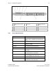
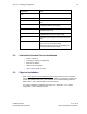
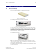
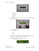
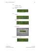
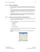
Table Of Contents
- 1 Introduction
- 2 Installation Steps
- 3 Step #1 – Configure Regions
- 4 Step #2 – Preparing for Installation
- 5 Step #3 – Installing the Appliance
- 6 Step #4 – Installing the Bridge
- 7 Step #5 – Installing the Sensors
- 8 Step #6 – Installing the Tags
- 9 Step #7 – Associating the Tags with Assets
- 10 Step #8 – System Testing and Quality Control
- 11 Adding Additional Assets After Installation
- 12 Troubleshooting

Step #3 – Installing the Appliance 21
Installation Guide v2.3 – 5/10
Confidential and Proprietary ©2010, Awarepoint Corporation
Figure 26 - Awarepoint Appliance Diagram - Front (Dell PowerEdge 1950)
1
Power-on indicator, power
button
2 NMI button 3 System identification
button
4
LCD display 5 USB connectors (2) 6 Video connector
7
Hard drives 8 Optical drive
5.1.1 Server Specifications
Component Detail
Base Unit Quad Core Xeon E5405 Processor2x6MB
Cache, 2.0GHz, 1333MHz FSB, PE1950 (467-
5794)
Processor Information,No Second Processor (311-1193)
Memory 2GB 667MHz (4X512MB), Single Ranked
DIMMs (311-6153)
Keyboard No Keyboard Selected (310-5017)
Video Card LOM NICs are TOE Ready (430-2968)
Video Memory Riser with 2 PCIe Slots for PowerEdge 1950
(320-4648)
Hard Drive 73GB 10K RPM Serial-Attach SCSI 3Gbps 2.5-
in HotPlug HardDrive (341-3055)
Hard Drive Controller PERC6i SAS RAID Controller 2x4 Connectors,
Int, PCIe 256MB Cache (341-5781)
Operating System No Operating System (420-6320)
NIC Dual Embedded Broadcom NetXtreme II 5708
Gigabit Ethernet NIC (430-1762)