
User's Manual

5
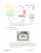
Figure 1-1.1: System Diagram
The System is configured using the System Manager, a Java application that runs
on a PC connected to the facility LAN. The System Manager may be
downloaded from the Awarepoint Appliance.
1.3.1 Awarepoint Bridge
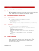
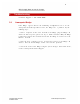
The Bridge model B2 is shown.
Figure 1.1-2: Awarepoint Bridge model B2
The connectors on the bottom of the bridge are (Left to Right) Network
Interface, Power Connector, and Serial Port. The Network Interface connects the
Bridge to the Ethernet
network, according to IEEE standard 802.3. The power
connector connects to the
Awarepoint power adapter. The Serial Port is used
for configuring the Bridge. The serial interface operates on 38,400 baud with 8
data bytes, 1 stop bit, and no parity.
Awarepoint Bridge model B2 © 2008 Awarepoint Corporation
Installation Manual