
User Manual
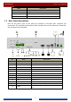
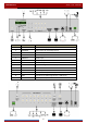
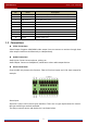
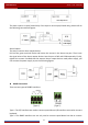
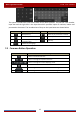
Table Of Contents
- Contents
- 1 Introduction
- 2 Basic Operation Guide
- 3 Wizard & Main Interface
- 4 Camera Management
- 5 Live Preview Introduction
- 6 PTZ
- 7 Record & Disk Management
- 8 Playback & Backup
- 9 Alarm Management
- 10 Account & Permission Management
- 11 Device Management
- 12 Remote Surveillance
- Appendix A FAQ
- Appendix B Calculate Recording Capacity
- Appendix C Compatible Device List

Introduction
DVR User Manual
8
The alarm input is an open/closed relay. If the input is not an open/closed relay, please refer to
the following connection diagram:
Alarm Output:
The way to connect alarm output device:
Pull out the green terminal blocks and loosen the screws in the alarm-out port. Then insert
the signal wires of the alarm output devices into the port of NO and COM separately. Finally,
tighten the screws. Provided that the external alarm output devices need power supply, you
can connect the power supply as per the following figures.
RS485 Connection
There are two types of RS485 interfaces:
(Type 1) (Type 2)
Type 1: The P/Z interfaces are used to connect speed dome. K/B interfaces are used to connect
keyboard.
Type 2: The RS485 interfaces are not only used to connect speed dome but also to connect