
Manual


Room Alert 3E
10 AVTECH Software, Inc.
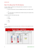
Sensor Display Area
In the main viewing pane of the “Status” tab is the “Sensor Display Area.” Here you may view
the current readings for your sensors, which are displayed left to right as follows:
Channel 1:
Internal Temperature Sensor
Channel 2:
External Digital Sensor
Channel 3:
External Switch Sensor
Below the channels, you see the status icons and the labels for your sensors, which you may
configure in Settings Æ Sensors.
Status Icons
Green circle with “9” mark…....... Sensor is in a clear state.
Grey circle……………………...... Sensor has no alarm threshold set.
Red circle with “X” mark…........... Sensor is in an alarm state.
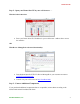
Display All Sensors / Connected Sensors
If you have no external digital sensor connected, you may temporarily hide Channel 2.
1. To hide the disconnected digital sensor, click Connected Sensors in the “Current
Sensors Status Bar” as shown here.
2. To toggle the view back to all 3 sensor channels, click All Sensors.
The “Sensor Display Area” collapses and expands as shown below: