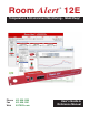
Room Alert 12E ® Temperature & Environment Monitoring... Made Easy! Phone Fax Web 401.628.1600 401.628.1601 AVTECH.com User’s Guide & Reference Manual 130401.
Protect Your IT Facility... Don’t Wait Until It’s Too Late! Monitor, Alert... Log, Graph... View, Respond... Report, Plan! Install Room Alert & TemPageR...
On behalf of the entire team at AVTECH, we say, “Thank You!” It is our privilege to serve you, our valued customer.
Copyright Information Copyright 1988-2013 AVTECH Software Inc. All Rights Reserved. No part of this book may be used or reproduced for commercial benefit in any form or by any means, or stored in a database or retrieval system, without prior written permission of AVTECH Software Inc., except in the case of brief quotations embodied in articles and reviews.
Room Alert 12E Table of Contents Introduction To Room Alert 12E .....................................................................................................3 Room Alert 12E Package Contents..................................................................................................4 The Room Alert 12E ID Box .....................................................................................................4 Front ..............................................................................
Room Alert 12E Help ..........................................................................................................................................41 About........................................................................................................................................42 Updating & Troubleshooting Your Room Alert 12E ....................................................................43 How To Download Firmware & Software Updates From AVTECH.com ............................
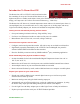
Room Alert 12E Introduction To Room Alert 12E The Room Alert 12E is AVTECH’s mid-sized monitor that has something for everyone. It boasts all the features of our highest-end unit on a smaller scale and at a lower price. With the Room Alert 12E, AVTECH brings you Temperature & Facilities Environment Monitoring… Made Easy.
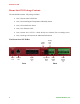
Room Alert 12E Room Alert 12E Package Contents The standard Room Alert 12E package includes: • One (1) Room Alert 12E ID Box • One (1) External Digital Temperature & Humidty Sensor • One (1) External Power Sensor • One (1) 10' Ethernet Cable • One (1) Room Alert 12E User’s Guide & Reference Manual (You’re reading it now.
Room Alert 12E Front Power Port A standard power port connects Room Alert 12E to an electrical outlet with AVTECH’s International Power Adapter. NOTE Look for the AVTECH logo. Using another power adapter could damage the Room Alert 12E’s circuit board and void the warranty. If you need one, purchase it online at AVTECH.com. AVTECH has an international power adapter with a compatible plug style for each and every country.
Room Alert 12E Back Reset Button A small push button resets Room Alert 12E to factory default settings. Light Tower & Relay Adapter Port A standard RJ-11 jack connects a Light Tower & Relay Adapter to your Room Alert 12E via a standard RJ-11 (straight through) telephone cord. Relay Output Port A set of contacts connects any low-voltage device to your Room Alert 12E via standard speaker wire.
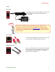
Room Alert 12E How To Install Your Room Alert 12E Step 1: Connect Your Room Alert 12E Hardware If Your Network Is Power Over Ethernet (PoE) Enabled • Connect one end of a standard Ethernet cable to the Room Alert 12E’s Ethernet port. • Connect the other end to a PoE-enabled network jack. That’s it! Your Room Alert 12E is now powered and discoverable on your network. If Your Network Is Not Power Over Ethernet (PoE) Enabled A.
Room Alert 12E Step 2: Open And View Your Room Alert 12E In Your Web Browser With The Built-In Interface • Enter your Room Alert 12E’s IP address in your web browser’s address bar to access the interface. OR With Device Manager For Advanced Functionality 8 • Download and install AVTECH’s Device ManageR via your customer account at AVTECH.com/Downloads. • Launch it in your web browser at http://localhost:8080. AVTECH Software, Inc.
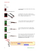
Room Alert 12E Step 3: Install Additional Components Connect Included External Sensors AVTECH’s external Digital Temperature Sensor and Power Sensor, shown here, come standard with the Room Alert 12E package. Digital Temperature Sensor Power Sensor Please install them according to the Installation Notes included with them. Connect Other Compatible Components If you purchased additional components that are compatible, install them according to the Installation Notes included with them.
Room Alert 12E How To Use Room Alert 12E’s Web Interface You may configure your Room Alert 12E through its built-in web interface. To access the interface, you may either: • Select your Room Alert 12E in Device ManageR and click the “Open Web” button. or • Type the IP address of your Room Alert 12E monitor directly into the address bar of your web browser.
Room Alert 12E Current Sensor Status Bar Below the Status tab is the “Current Sensor Status Bar,” where you may view basic information about your Room Alert 12E and make temporary adjustments to the sensor display. • You may find your Room Alert 12E’s name, current date & time, and MAC address here. • To determine if your Room Alert 12E’s firmware is current, you may click Room Alert 12E vX.X.X at the right. TIP Your Room Alert 12E must be connected to the internet in order to check firmware versions.
Room Alert 12E Sensor Display Area In the main viewing pane of the Status tab is the “Sensor Display Area.” Here you may view the current readings for your sensors, which are displayed in a grid on the screen as follows: Relay Output Digital Sensors (includes Analog Input when enabled in Settings) Light Tower or Relay Switch Sensor (when enabled in Settings) Switch Sensors With each sensor are displayed the status icons and labels, which you may configure in Settings Æ Sensors.
Room Alert 12E Settings To access your Room Alert 12E’s settings, click Settings in the navigation bar at the top of your screen. TIP You’ll see a prompt for your username and password whenever you click Settings. If you have not set up a password for your Room Alert 12E, simply click OK without entering anything. AVTECH Software, Inc.
Room Alert 12E Network Navigate to Settings Æ Network to open the “Network Settings” screen. Device Name To rename your Room Alert 12E: 1. Select the automatically-assigned name in “Device Name” and enter a new one of up to 15 alphanumeric characters. 2. Click Accept Changes at the bottom of your screen to temporarily save your settings. You may now navigate to another screen; however, if you close the web interface before the next step, you will lose your changes. 3.
Room Alert 12E IP Address Configuration—Static IP To assign a static IP address: 1. Select Use The Following IP Configuration. 1. In “IP Address,” enter the new static IP address. 2. In “Subnet Mask,” enter the subnet mask. 3. In “Default Gateway,” enter the gateway IP address. 4. In “DNS Server IP,” enter the DNS server IP address. 5. Click Accept Changes at the bottom of your screen to temporarily save your settings.
Room Alert 12E Ethernet Configuration Typically, you may leave the “Ethernet Configuration” section at the defaults, which are shown below, for immediate use of Room Alert 12E. However, if you connect your Room Alert 12E to a managed switch that controls your network traffic, you may need to change these settings: 1. In “MTU Size,” you may leave the default, 1024, or enter a value as low as 512. 2. You may uncheck “Auto Negotiate” and choose: • For “Speed,” 100 Mpbs or 10 Mbps.
Room Alert 12E 1. Check Email Enabled. 2. Leave the Email Footer Enabled checked to include AVTECH contact information with email messages. 3. Check Use SMS to send a shorter email with a reduced character count. 4. In “Mail Server Port,” enter your mail server’s SMTP port. The default is 25, a commonly-used port. 5. In “Timeout,” you may leave the default, 5 seconds, or enter another interval. 6. In the “Mail Server” field, enter the domain name or IP address of your mail server. 7.
Room Alert 12E TIP Your password cannot be more than 11 alphanumeric characters. Email Recipients (Separated By Comma) 11. In “Email Addresses,” enter the email and email-to-SMS addresses that you’d like to send alerts to. Separate each address with a comma. • Email address: ITMgr@YourCo.com • Email-to-SMS address: 1235551900@ATT.txt.net • Addresses separated by commas: ITMgr@YourCo.com, 1235551900@ATT.txt.net, etc. 12. Click Send Test Email.
Room Alert 12E Simple Network Management Protocol (SNMP) Because your Room Alert 12E is fully SNMP-compliant, you have the option to monitor it with a 3rd-party monitoring application capable of performing SNMP queries. You may configure the Room Alert 12E to send SNMP Traps in response to a change in alarm states to up to three host systems running 3rd-party SNMP monitoring applications.
Room Alert 12E SNMP Configuration To begin configuring your Room Alert 12E for SNMP: 1. In “Community Name,” you may leave the default SNMP protocol community name— “public”—or enter a new name. TIP The community name you assign here must match the one in your 3rd-party SNMP monitoring application. 2. You may leave “Contact (sysContact)” blank or enter a person’s name to specify who is receiving the information. 3.
Room Alert 12E SNMP Trap Sending Configuration You may configure your Room Alert 12E to send SNMP Traps in response to a change in alarm state to up to three host systems running 3rd-party SNMP monitoring applications. Each host system you enter in these fields will receive the same SNMP Traps simultaneously. To configure your Room Alert to send SNMP Traps: 1. In “Trap Send IP 1,” enter the IP address of the host system that runs your 3rd-party SNMP monitoring application. 2.
Room Alert 12E Navigate to Settings Æ Sensors to open the “Sensor Settings” screen. NOTE Notice the “Alarm Profile” drop-down menu next to each sensor. If you have a Light Tower (any model) or Relay Switch Sensor connected to your Room Alert via a Light Tower & Relay Adapter, you may configure Alarm Profiles. Please refer to the Alarm Options section in this manual for further information.
Room Alert 12E and a high threshold of 80º, your temperature sensor will alarm when the temperature rises above 80º and clear when it falls below 79º; likewise, with a low threshold of 60º, the sensor will alarm when the temperature falls below 60º and clear when it rises above 61º. Internal Sensor Alarm Configuration (Internal Temperature Sensor) You may configure alert thresholds for the Internal Digital Temperature Sensor in the “Internal Sensor Alarm Configuration” field.
Room Alert 12E NOTE If you have a Light Tower (any model) or Relay Switch Sensor connected to your Room Alert via a Light Tower & Relay Adapter, you may configure Alarm Profiles. Please refer to the Alarm Options section in this manual for further information. 6. Click Accept Changes at the bottom of your screen to temporarily save your settings. You may now navigate to another screen; however, if you close the web interface before the next step, you will lose your changes. 7.
Room Alert 12E 1. In “Sensor Label,” you may leave the default label, “Sensor 1,” or rename it to something more descriptive, such as “Ext Temperature.” 2. The “Alarm On” fields automatically match the type of sensor you connect. In this example, the “Alarm On” setting is Temperature. 3. Enter values in the “High” and “Low” field to set high and low thresholds. Your Room Alert 12E will generate alerts in response to these temperatures. 4.
Room Alert 12E Analog Sensor Settings You may configure your 0-5 VDC analog sensor in these fields. In the example below, we are configuring AVTECH’s Current Loop. TIP Work from right to left to configure the Analog Sensor. 1. In the set of fields on the right of the screen, click “Enable” to turn on the “Reference,” “Scale” and “Units” fields. • In “Reference,” enter values from 5 to 0 that represent the “High” and “Low” points of your analog sensor’s output signal range.
Room Alert 12E 2. In the set of four fields to the left of the screen, click “Enabled” to enable the sensor on the Room Alert web interface and Device ManageR software. • In “High” and “Low,” you may leave the default, 0—which means no alarm is configured—or enter values of up to 4 characters that fall within the “Scale” range from the previous step.
Room Alert 12E External Switch Sensor Settings 1–4 You may configure the alert state for the four external switch sensors in the “Switch Sensor Settings” fields. Shown below are the default settings for the four switch sensors. Your Room Alert 12E monitors your switch sensors for an “Open” or “Closed” circuit state. Room Alert defaults to alarming on “Closed,” as you can see above; you may, however, need to change that depending on the type of sensor.
Room Alert 12E 1. Click the Status tab at the top of your screen in the web interface. 2. Scroll down to the Switch Sensors and look at the circuit state of the channel you connected your sensor to. If you connected your sensor to the first switch sensor port on Room Alert, look at Channel 1; if you connected it to the second, look at Channel 2, etc. 3. Notice the circuit state of Switch 1. It should show the normal state, which in this case is “Closed.” (Ignore the red color coding for now.
Room Alert 12E 4. Click Accept Changes at the bottom of your screen to temporarily save your settings. You may now navigate to another screen; however, if you close the web interface before the next step, you will lose your changes. 5. Click Save Settings in the navigation bar to the left of your screen. Your Room Alert 12E will automatically reboot and commit your changes.
Room Alert 12E Light Tower / Relay Configuration In “Light Tower / Relay Configuration,” you may configure devices connected through your Room Alert 12E via the Light Tower & Relay Adapter. A Light Tower & Relay Adapter gives you the option to add an AVTECH Light Tower, Light Tower w/Audio or Relay Switch Sensor. You may also connect a low-voltage device directly to the built-in relay port on the Light Tower & Relay Adapter.
Room Alert 12E In this example, we’ll configure a Light Tower w/ Audio. 1. In “Light Tower / Relay Label,” you may leave the default, “Light Tower 1” or enter your own, such as “Server Rm RYG.” 2. In “Connected Light Tower / Relay,” select from the appropriate option from the choices in the drop-down menu. For this example, we are choosing Red/Yellow/Green w/Audio for the Light Tower w/Audio. 3. Once you choose your device, the “Alarm Profiles” grid beneath it expands.
Room Alert 12E Relay Action 1 Configuration Here you may set the device connected through the built-in relay output port to turn on or off in response to your Room Alert 12E rebooting or its sensors going in and out of alarm state. 1. In “Sensor Label,” you may leave the default, “Relay 1,” or enter something more descriptive, such as “Server Rm AC.” 2. In the “On Boot” column, you may select what the relay output does in response to the Room Alert 12E rebooting. The default is “Off.” 3.
Room Alert 12E 3. Click Accept Changes at the bottom of your screen to temporarily save your settings. You may now navigate to another screen; however, if you close the web interface before the next step, you will lose your changes. 4. Click Save Settings in the navigation bar to the left of your screen. Your Room Alert 12E will automatically reboot and commit your changes. TIP Alarm Profiles do not affect alerts sent by email or modem.
Room Alert 12E TIP Use only letters and numbers in your log in password—no special characters, please. 2. Re-enter the password in the “Confirm Password” field to verify. 3. Click Accept Changes at the bottom of your screen to temporarily save your settings. You may now navigate to another screen; however, if you close the web interface before the next step, you will lose your changes. 4. Click Save Settings in the navigation bar to the left of your screen.
Room Alert 12E Advanced You may configure a number of advanced options here, including Status screen defaults, Device ManageR “Push,” time & date, and trace output. Navigate to Settings Æ Advanced to open the “Advanced Settings” screen. 36 AVTECH Software, Inc.
Room Alert 12E Status Page Configuration You may set defaults for the Status screen here. 1. In “Refresh Rate (seconds),” enter the number of seconds you would like the Status screen to refresh at. You may enter a value from 1 to 65535. The default is 60 seconds (i.e., every 1 minute). 2. In “HTTP Port,” you may change the port number your web browser uses to connect to your Room Alert’s web interface. It uses port 80 by default. 3.
Room Alert 12E • Your Room Alert 12E can immediately send an update to Device ManageR when it detects an alarm, regardless of any intervals you have configured either in this section or in the Device ManageR discovery interval. To enable Push to Device ManageR from your Room Alert 12E: 1. Select Enable Device ManageR Push. 2. In “Server IP Address,” enter the IP address of Device ManageR’s host system. 3. In “Server Port,” enter the port Device ManageR uses. The default is 8080. 4.
Room Alert 12E 1. In “Time Zone,” select your time zone from the drop-down list. Greenwich Mean Time (GMT) is the default. 2. In “Time Format,” you may select either the MM/DD/YY or DD/MM/YY date format from the drop-down list. Month first is the default. 3. In “Time Display,” you may select the 12- or 24-hour format from the drop-down list. The 24-hour setting is the default. 4. Select Daylight Savings if you would like your Room Alert 3E time setting to compensate by +1 hour for daylight savings time. 5.
Room Alert 12E • You may manually synchronize the time by clicking Update Now. Clicking this button does not affect the “Auto Refresh” interval. 7. Click Accept Changes at the bottom of your screen to temporarily save your settings. You may now navigate to another screen; however, if you close the web interface before the next step, you will lose your changes. 8. Click Save Settings in the navigation bar to the left of your screen. Your Room Alert 12E will automatically reboot and commit your changes.
Room Alert 12E Help Click the Help tab to open the Room Alert 12E Help screen, which provides helpful links and contact information for AVTECH support resources. You may find the version number and release date of the firmware that is installed on your Room Alert 12E on this screen. To check if your Room Alert 12E has the most current version, click Click Here To Check For Updates. TIP Your Room Alert 12E must be connected to the internet in order to check for newer firmware versions. Thank you.
Room Alert 12E About Click the About tab to open the Room Alert 12E About screen, which provides helpful links and contact information for AVTECH sales and support resources. You may find the version number and release date of the firmware that is installed on your Room Alert 12E on this screen. To check if your Room Alert 12E has the most current version, click Click Here To Check For Updates. TIP 42 Your Room Alert 12E must be connected to the internet in order to check for newer firmware versions.
Room Alert 12E Updating & Troubleshooting Your Room Alert 12E How To Download Firmware & Software Updates From AVTECH.com Software and firmware updates are available to licensed customers with current “Maintenance Support & Update Service” (MSUS). To download: 1. Go to AVTECH.com/Downloads, or click Downloads on the menu bar at the top of the screen at AVTECH.com. 2.
Room Alert 12E TIP IMPORTANT: Be sure that there are no web browsers accessing your Room Alert 12E monitor from anywhere on your network before uploading the firmware as this could cause the firmware update to be incomplete or become corrupted. How To Discover Room Alert 12E When Your Network Blocks UDP Broadcasts If your network blocks UDP broadcast packets on port 30718, AVTECH’s Device ManageR might not be able to automatically locate the Room Alert 12E monitor.
Room Alert 12E 2. Click Reset Defaults in the navigation bar to the left. 3. Click Yes when prompted with “Are you sure you want to Reset Factory Defaults?” 4. Your Room Alert 12E will automatically reboot and attempt to obtain an IP address via DHCP. 5. To automatically discover your Room Alert 12E on your network, open AVTECH’s Device ManageR. (If you don’t already have it installed, download it from your customer account at AVTECH.com/Downloads.
Room Alert 12E Introduction To AVTECH’s Device ManageR Device ManageR is AVTECH’s all-in-one software solution for the discovery, management, monitoring, alerting, logging, graphing, automatic action and more of AVTECH’s physical environment monitoring hardware and Axis network cameras. Manage Unlimited Room Alert & TemPageR Montiors 9 Control all of your Room Alert and TemPageR units from a single web browser interface, accessible from anywhere by internet.
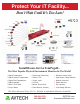
IT & Facilities Environment Monitoring Made Easy! Digital Sensors are those that monitor in real-time to provide digital values that can be viewed through a web or application interface, passed in alert notifications or logged for creating charts and graphs. Common digital sensors include Temperature; Outdoor Temperature; Fluid Temperature; and Temperature & Humidity. ST BE S Digital Temperature Sensor • Real-time temperature sensor. • Max sensor cable distance up to 100´, includes 25´.
ST BE Flood Sensor w/8´ Cable 8´ Flood Cable Extension 15 50 $2 R LE L SE IT & Facilities Environment Monitoring Made Easy! $1 AVTECH Sensors • Real-time recognition of water/flood anywhere along the length of the patented flood cable. • Real-time recognition of water/flood anywhere along the length of the patented flood cable. • 8´ Flood Cable with 25´ RJ-11 leader cable. • Can be extended by adding additional 8´ extensions. • Alert triggered when sensor is activated or power lost.
BE Air Flow 1 Sensor (NC) Air Flow 2 Sensor (NO) 0 0 $4 ST R LE L SE IT & Facilities Environment Monitoring Made Easy! $4 AVTECH Sensors • Real-time recognition of air flow stop/start. • Real-time recognition of air flow stop/start. • Use in HVAC duct, under raised floors, or near fan. • Use in HVAC duct, under raised floors, or near fan. • Max sensor cable distance up to 900´, includes 25´. • Max sensor cable distance up to 900´, includes 25´.
IT & Facilities Environment Monitoring Made Easy! • Light Tower lights turn on when alarms are detected (i.e. pings fail, high temps, etc.). 79 $2 ST BE R LE 50 • Light Tower lights turn on when alarms are detected (i.e. pings fail, high temps, etc.). • Lights turn on/off via SNMP set, URL & interactively via AVTECH’s Device ManageR software. • Lights turn on/off via SNMP set, URL & interactively via AVTECH’s Device ManageR software. • Includes 3´ Light Cable; no extension cable available.
How To Purchase AVTECH Products AVTECH products are available for purchase around the world and used in 106 countries, on Antarctica and in space. You can purchase through your favorite reseller *, direct from AVTECH, or online through our store. When ordering from AVTECH, we are happy to accept your organization’s purchase order (PO), as well as payment via credit card or wire transfer. All orders ship the same or next business day.
AVTECH.com Protect Your IT Facility...