
Technical data


PAGE 55
Windows PC Software
5.7.2.1.6 Relay / TTL
The MAGIC TH2plus system incorporates four GPIO Pins (TTL) which can
be programmed separately as input or output. Additionally, two Relays are
available.
The operating mode of a TTL Pin - Input or Output - is selected via the option
Direction.
The following specification accounts for all three configuration windows
TTL1, TTL2, TTL3 and TTL4.
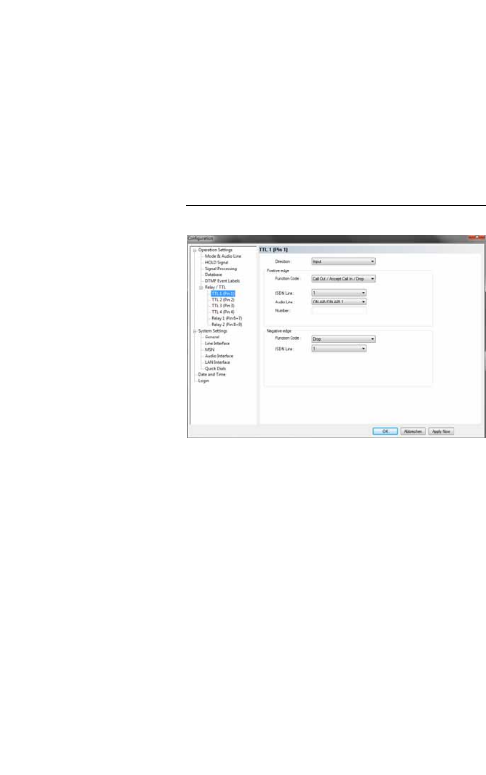
TTL Pin as input
FIG. 36 TTL PIN AS INPUT
If you use a TTL Pin as Input, you can program two different functions sepa-
rately when edges change:
• Positive edge: The event is activated when the voltage on the TTL Pin
changes from 0V to +3.3V.
• Negative edge: The event is activated when the voltage on the TTL Pin
changes from +3.3V to 0V.
The following functions can be configured (Function Code):
– - : No function, the Pin is not used.
– Call Out/Accept Call In/Drop: Via this function you can establish a
connection to a certain Phone Number, accept an incoming call or drop
a call. Under POTS Line/ ISDN Line you select the line (1 or 2) on
which the connection is established. Under Audio Line you select the
Audio line which is activated when the call is accepted.
– Call Out (Level Trig.): Same function as above, however, except that
here the level is analysed and not the edge (level triggered).
– Drop: If you activate this function, a connection on the selected line (1
or 2) can be dropped.