
Technical data


PAGE 82
MAGIC TOUCH Software
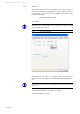
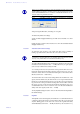
systems. On both systems connect pin 1 and pin 5 of the USER IO interface as
shown in Fig. 54. When switching over, one system now gets the valid MSN-1
block and the other gets the invalid MSN-2 block. Thus, always, only one sys-
tem is active.
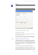
To recognise on the MAGIC TOUCH user interface which MSN is active, the
name of the MSN block selected by the system, is displayed in the title bar of
the main window. The names of the MSN blocks can be entered in the MSN 1
Name and MSN 2 Name fields.
FIG. 54 REDUNDANT OPERATION VIA MSN-BLOCK SWITCHING
If the system is active the number of lines, as defined in the ISDN configura-
tion, is displayed on the MAGIC TOUCH user interface (see CHAPTER
7.7.3.4, page 73).
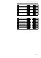
If free lines are still available, the inactive system can still be used simulta-
neously for advanced production. The MAGIC TOUCH user interface dis-
plays the relevant lines for the active and inactive systems as per TAB. 5 and
TAB. 6. If an odd number of call forwarding channels is used, the active sys-
tem always gets an additional call forwarding channel.
TAB. 4 EXAMPLE OF MSN ENTRIES (VALID FOR BOTH SYSTEMS)
MSN-1 MSN-2
S
0
1 5271189 1111111
5271189 1111111
S
0
2 5271219 1111111
5271219 1111111
L
The configuration of the ISDN lines (see CHAPTER 7.7.3.4, page 73) with the
parameters Number of B Channels visible, First B Channel used for Call For-
warding and Number must be identical on both systems.
POWER 115/230V
0 I
EXTENSION BUS
USER I/O
HSDLSD
RS232C
OUT CMD IN
So
12
POWER 115/230V
0 I
EXTENSION BUS
USER I/O
HSDLSD
RS232C
OUT CMD IN
So
12
ISDN BUS
PIN 5: EARTH
Pin 1 and 5 open: active Pin 1 and 5 closed: inactive
PIN 1
S
0
2
S
0
1