
Technical data


PAGE 145
Interfaces
A4.2 RS232C Interface
The RS232C interface is used for configuring and monitoring the MAGIC
ISDN Telephone Hybrid systems with a PC. To connect the system to the PC, a
null modem cable, in which pin 2 and pin 3 are crossed, is required. Addition-
ally, pin 5 GND, must be connected. All other pins are not required.
A4.3 TTL USER I/O Interface
External operating signals can be sent through this interface. Three signals are
always used to drive the relay within the system.
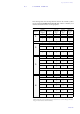
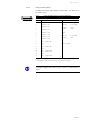
TAB. 15 PIN ASSIGNMENT: RS232 INTERFACE
Connector: RS-232C (SUB-D, 9-pole)
Pin Signal Electrical characteristics
1Not usedType:DTE
Level: V.24
Data rate: 19200 Baud
Transmission range:max. 15 m
Protocol: 1 Start bit
8 Data bits
1 Parity bit
1 Stop bit
2RXDReceive Data
3TXDTransmit Data
4 DTR Data terminal ready
5 GND Ground
6 DSR Data set ready
7 RTS Request to send
8CTSClear to send
9Not used
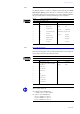
TAB. 16 PIN ASSIGNMENT: USER I/O INTERFACE
Connector: TTL USER I/O (SUB-D, 9-pole)
Pin Signal Electrical characteristics
1 MSN switchover input
+5V: MSN-1 (level without switching)
GND: MSN-2
Level: TTL/CMOS
Rating: 20 mA
2 used for relay 1
3 TTL_3_IN/OUT
4 used for relay 2
5GND
6 TTL_5_IN/OUT
7 used for relay 3
8 TTL_7_IN/OUT
9 TTL_8_IN/OUT
L
When using Slave systems, this interface is also used for the hardware dongle
(Slave 1, Slave 2, Slave 3):
Pin 9: Master/Slave identification
0 (GND) = Slave, 1 (+5V) = Master
Pin 1, Pin 2 = Slave identification
Pin 2 = 0 and Pin 1= 0: Slave 1
Pin 2 = 0 and Pin 1=1: Slave 2
Pin 2 = 1 and Pin 1=0: Slave 3
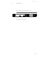
1
5
6
9
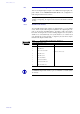
1
5
6
9