
User Guide
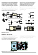
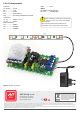

Figure 1. Schematic diagram
Figure 2. Arrangement of components on the PCB
output active as long as motion is detected. Whilst,
the jumper in the "L" position configures the detector
in such a way that once any motion is detected, the
detector output remains activated for a preset time
according to the potentiometer setting. Reactivation
of the sensor is possible after approximately 3
seconds. The detector's operating range can be
adjusted via a potentiometer, which is mounted closer
to the configuration jumper, from approximately 3 to
7m. The second potentiometer adjusts the detector's
activation duration when object movement is
detected, between 5 and 200 seconds. Operation of
the module starts as soon as the supply voltage is
applied. The actuating element is a T1 transistor of
type IRL3705. Lighting time of the light source
connected to the output can be adjusted via
potentiometer PR1 from approximately 15 seconds to
approximately 8 minutes. Each time movement is
detected, the time starts counting down from the
beginning. Function of the motion detection indicator
is performed by LED.
The unit must be mounted on a 33x65mm PCB, the
mounting diagram is shown in Figure 2. Start
mounting the circuit by soldering resistors and other
small components onto the board, and finish by
assembling the socket, electrolytic capacitors,
transistor, screw terminals and PIR module. Once
assembled, the system is immediately ready for use,
requiring only the appropriate configuration.
Mounting and start-up
2