
Manual


RELAY PANEL CONNECTIONS
J connects to J on main board (already connected)
K connects to K on main board (already connected)
P2 connects to P2 on main board (already connected)
P3 connects to P3 on main board (already connected)
2CN1 30 AMP CONNECTOR
L = 24Vac supply input LIVE
N = 240Vac supply input NEUTRAL
E = input EARTH
Note: It is recommended that the supply to CN1 is taken from
a separate 30 amp ELCB/RCCD in the on site consumer unit.
2CN2 30 AMP OUTPUR CONNECTOR
L = 240Vac controlled output LIVE
N = 240Vac controlled output NEUTRAL
E = output EARTH
2CN3: Live, neutral and earth connections to TX1 primary
(already connected).
TRAFFIC LIGHT REMOTE DISPLAY (952.804)
A, B, C, D connect to corresponding connectors on main panel
(240Vac mains powered displays should be supplied via 5
amp switched spur or similar to Euro connector, low voltage
connections, A, B, C, D still connect to A, B, C, D respectively on
main panel).
This unit is to be installed by qualied persons only.
All wiring should conform to current regulations.
All earth connections should be made and tested before use.
Disconnect supply before servicing.
w w w . s k y t r o n i c . c o . u k
w w w . s k y t r o n i c . c o m
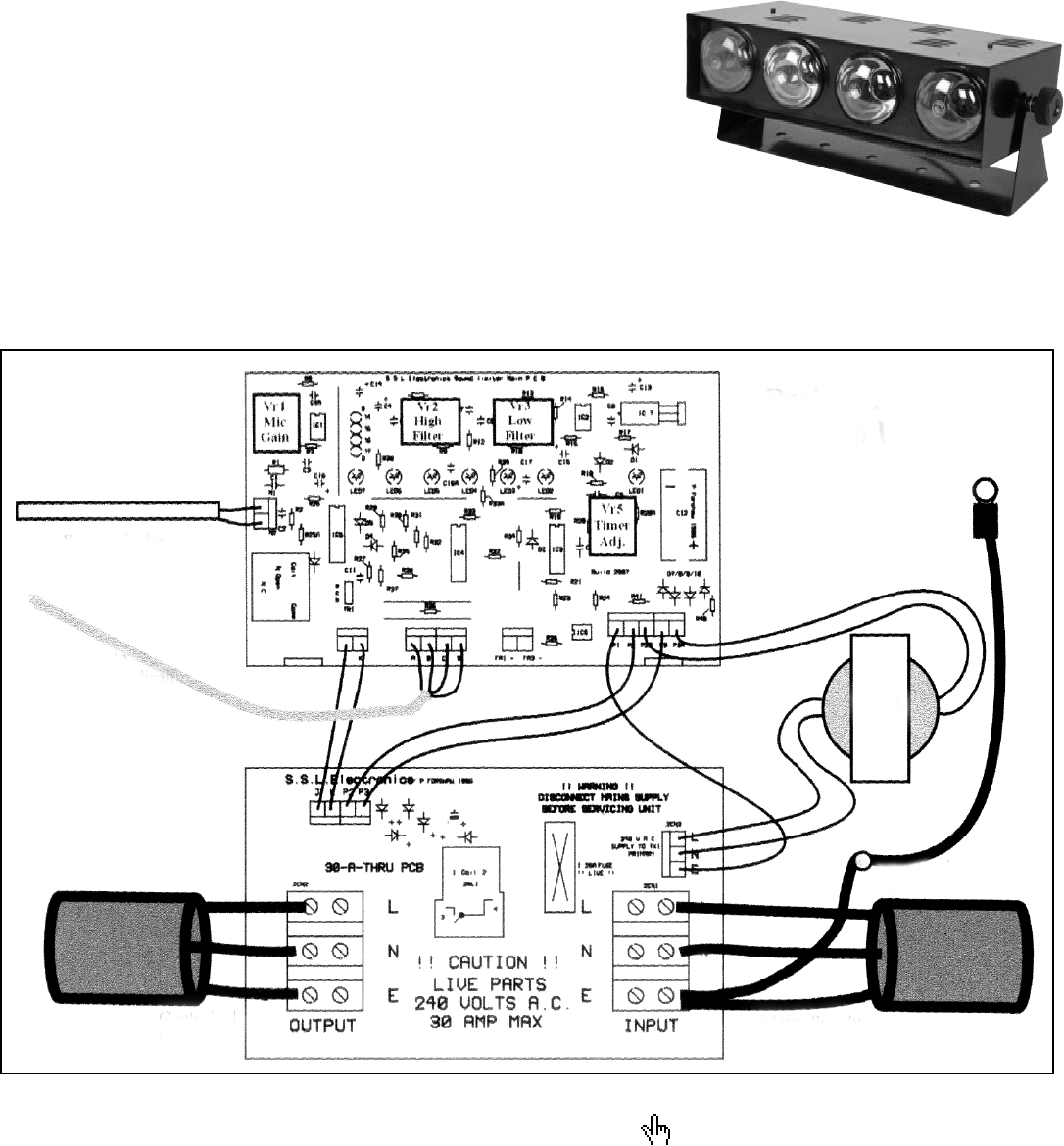
BASIC WIRING
30 Amp Unit
Lid Eyelet
Case Earth Stud
Mains Supply InputControlled Output
Screened Mic Cable
4-core to
Remote Indicator
TX1