
Repair manual

SULEV 2.0L TFSI Engine
30
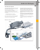
Testing the System
The California Air Resources Board (CARB) requires that
the secondary air system be monitored during the heat-
up phase of the catalytic converter.
Previously, the system was monitored using the oxygen
sensor. However, this downstream sensor does not
become available quickly enough. For this reason, the
system is monitored and evaluated for pressure-based
secondary air diagnosis by Secondary Air Injection Sensor
1 G609.
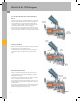
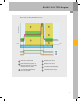
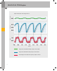
Pressure-Based Secondary Air Diagnosis
Process
Phase 0
The control module initialization process begins at
“ignition on.” The signal from Secondary Air Injection
Sensor 1 G609 is stored and compared to the signals
received from the ambient pressure sensor and the intake
manifold pressure sensor.
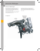
Phase 1
When the secondary air mass is injected, the pressure
within the secondary air system also rises to above
atmospheric pressure. This pressure increase is
determined by G609. The resulting analog signal is
evaluated by the ECM. If the signal exceeds the pre-
defined limit, for example due to a blockage in the
system or leakage, a DTC entry will be generated. Engine
Electronics Indicator Lamp K149 will also be activated. If
the system is still in order, the diagnosis procedure will
be continued.
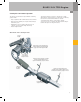
Phase 2
During this phase, Secondary Air Injection Valve N112 is
closed and checked for leaks. The value determined by
Secondary Air Injection Sensor 1 G609 is evaluated for
this purpose.
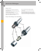
Phase 3
The secondary air pump is shut OFF and Secondary Air
Injection Valve N112 closed. The difference between the
actual measured pressure and the stored value generated
in phase 0 is evaluated.
A faulty Secondary Air Injection Pump (pump does not
shut off) or a faulty Secondary Air Injection Sensor 1 G609
can thus be detected.
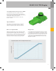
Reference
On the next page you will find a diagram
showing the individual phases of the
secondary air diagnosis process.