Single port KVM over IP switch Single Port KVM over IP SWITCH USER’S MANUAL Rev 1.
Single port KVM over IP switch TABLE OF CONTENTS 1. THE QUICK INSTALLATION GUIDE 2. INTRODUCTION 2.1 2.2 2.3 2.4 2.5 2.6 2.7 When the sever is up and running When the server is dead Features Package contents Technical specifications System requirement Cable diagrams 3. HARDWARE INSTALLATION 3.1 3.2 3.3 3.4 Operation overview Connecting IP- KVM to the host system Connecting IP- KVM to multi-port KVM switch Connecting External Reset/Power option 4. CONFIGURATION 4.1 Initial Configuration 4.1.
Single port KVM over IP switch 6.1 Remote Control 6.1.1 KVM Console 6.1.2 Remote Power 6.1.3 Telnet Console 6.2 Virtual Media 6.2.1 6.2.2 6.2.3 6.2.4 6.3 Floppy Disk CD ROM Drive redirection Options User Management 6.3.1 Change Password 6.3.2 Users And Groups 6.4 KVM Settings 6.4.1 6.4.2 6.4.3 6.4.4 6.5 Device Settings 6.5.1 6.5.2 6.5.3 6.5.4 6.5.5 6.5.6 6.5.7 6.
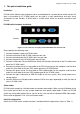
Single port KVM over IP switch 1. The quick installation guide Installation IP-KVM switch redirects local keyboard, mouse and video data to a remote administration console. All data is transmitted via IP. IP-KVM switch can be used in a multi administrator and multi server environment as well. Besides, IP-KVM switch is a KVM switch, which can also be used with a local console.
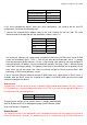
Single port KVM over IP switch Parameter IP auto configuration IP-Address Net-mask Default-Gateway Value DHCP 192.168.1.22 255.255.255.0 none Table 1-1: Initial configuration If this initial configuration doesn’t meet your local requirements, you need to do the initial IP configuration. Use one of the following ways: 1. Connect the enclosed NULL modem cable to the serial interface on the rear side.
Single port KVM over IP switch supply a Java Runtime Environment version 1.1 or higher. However, it is strongly recommended to install Sun JVM 1.4. The Remote Console will behave exactly the same way as if you were sitting directly in front of the screen of your remote system. That means that both the keyboard and mouse can be used in the usual way. Open the console by selecting the preview picture on the main site of the HTML front end. Figure 1-2 shows the top of the Remote Console.
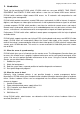
Single port KVM over IP switch 2. Introduction Thank you for purchasing IP-KVM switch. IP-KVM switch can save your MONEY, TIME, SPACE, EQUIPMENT and POWER. IP-KVM switch defines a new class of remote KVM access devices. IP-KVM switch combines digital remote KVM access via IP networks with comprehensive and integrated system management. IP-KVM switch provides convenient, remote KVM access and control via LAN or Internet.
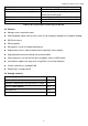
Single port KVM over IP switch Type of failure Hard disk failure Power cable detached, power supply failure CPU Controller, main board failure. CPU fan failure RAM failure Detected by Console screen, CMOS set-up information Server remains in power on state after power on command has been given. Power supply is on, but there is no video output. By server specific management software Boot-Sequence on boot console Table 2-1:Host system failures and how they are detected. 2.3.
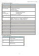
Single port KVM over IP switch 2.5. Technical specifications Model No.
Single port KVM over IP switch 2.7. Cable diagrams PS/2 Cable: Mini Din 6 pin Male to Male VGA Cable: HDB15 pin Male to Male USB 2.
Single port KVM over IP switch 3. Hardware installation 3.1 Operation Overview Figure 3-1 shows the connections of IP-KVM switch to its host, to peripheral devices, to the power source and to the local area network. Single port IP-KVM KVM PC IP Network Administrator Figure 3-1.a: IP-KVM switch usage scenario Single port IP-KVM KVM 8/16 PS/2 IP Network KVM Switch 8/16 Administrator Figure 3-1.
Single port KVM over IP switch Step 2 Connect the monitor to the IP-KVM switch console side. Step 3 Connect the keyboard to the IP-KVM switch console side. Step 4 Connect the mouse to the IP-KVM switch console side. Step 5 Connect a VGA cable (15-pin HDDB Male / Male) with the Male side to both of the PC and the host of the IP-KVM switch. Step 6 Connect one end to the PS/2 mouse port on the computer, and the other end to the host PS/2 mouse port on the IP-KVM switch.
Single port KVM over IP switch Step 8 (Option) Connect the type A connector of USB A-B cable to the USB port of the host system, while using remote mass storage control. USB type A plug of USB A-B cable to the computer. Step 8 Connect Ethernet and/or modem or both communication ports simultaneously, depending on how you want to access IP-KVM switch INTERNET Modem 3.2.1 Ethernet connection The rear side of IP-KVM switch provides a RJ-45 connector for Ethernet.
Single port KVM over IP switch ¾ Make sure that the cable is wired appropriately for a standard 100BASE-TX adapter. ¾ Align the RJ-45 plug with the notch on the adapter’s connector and insert it into the adapter’s connector. 3.3 Scenario of connecting IP-KVM switch to the Multi-port KVM Switch system 3.
Single port KVM over IP switch 4. Configuration 4.1 Initial Configuration The IP-KVM switch's communication interfaces are all based on TCP/IP. It comes pre-configured with the IP configuration listed in Table 4-1. Parameter IP auto configuration IP-Address Net-mask Default-Gateway Value DHCP 255.255.255.0 none Table 4-1. Initial network configuration Warning If the DHCP connection fails on boot up, the IP-KVM switch will not have an IP address.
Single port KVM over IP switch Figure4-1. IP-KVM switch setup tool On the upper left corner, the MAC address of the IP-KVM switch is displayed. To detect the MAC address, manually, press the button “Refresh Devices”. The displayed MAC address is the same MAC address printed on the white sticker placed on the back of the IP-KVM switch. If the IP-KVM switch is connected via USB, it is classified as an USB device and an appropriate drive letter is chosen for this device.
Single port KVM over IP switch 4.1.2 Initial configuration via serial console Using a serial terminal, the IP-KVM switch has a serial line interface (host side). This connector is compliant with the RS 232 serial line standard. The serial line has to be configured with the parameters given in Table 4-2. When configuring with a serial terminal, reset the IP-KVM switch and immediately press the “ ESC ” key. You will see some device information, and a “ => ” prompt.
Single port KVM over IP switch 4.1.3.1 IP-KVM switch keyboard settings The IP-KVM switch settings for the host's keyboard type have to be corrected in order to make the remote keyboard work properly. Check the settings in the IP-KVM switch front-end. See section 6.4.3 in details. 4.1.3.2 Remote Mouse Settings A common problem with KVM devices is the synchronization between the local and remote mouse cursors. The IP-KVM switch addresses this situation with an intelligent synchronization algorithm.
Single port KVM over IP switch While the IP-KVM switch works with accelerated mice and is able to synchronize the local with the remote mouse pointer, there are the following limitations, which may prevent this synchronization from working properly: Special Mouse Driver There are mouse drivers which influence the synchronization process and lead to desynchronized mouse pointers. If this happens, make sure you do not use a special vendor-specific mouse driver on your host system.
Single port KVM over IP switch 4.1.3.7 Video Modes The IP-KVM switch recognizes a limited number of common video modes. When running X11 on the host system, please do not use any custom mode lines with special video modes. If you do, the IP-KVM switch may not be able to detect them. We recommend using any of the standard VESA video modes, instead.
Single port KVM over IP switch 5. Usage 5.1 Prerequisites The IP-KVM switch features an embedded operating system and applications offering a variety of standardized interfaces. This chapter will describe both these interfaces, and the way to use them in a more detailed manner. The interfaces are accessed using the TCP/IP protocol family, thus they can be accessed using the built-in Ethernet adapter. The following interfaces are supported: HTTP/HTTPS Full access is provided by the embedded web server.
Single port KVM over IP switch Figure 5-1. The Internet Explorer displaying the encryption key length Newer web browsers do support strong encryption on default. 5.2 Login into the IP-KVM switch and logout 5.2.1 Login into the IP-KVM switch Launch your web browser. Direct it to the address of your IP-KVM switch, which you configured during the installation process.
Single port KVM over IP switch Warning The user “ super ” is not allowed to login via the serial interface of the IP-KVM switch. Warning Please make sure to change the super user password immediately after you have installed and accessed your IP-KVM switch for the first time.
Single port KVM over IP switch Open the IP-KVM switch remote console. Exit from the IP-KVM switch front end. Table 5-2. Buttons from the front end Warning If there is no activity for half an hour, the IP-KVM switch will log you out, automatically. A click on one of the links will bring you back to the login screen. 5.2.2 Logout from the IP-KVM switch This link logs out the current user and presents a new login screen.
Single port KVM over IP switch configured, the Remote Console is very unlikely to be able to establish the according connection. This is because today's web proxies are not capable of relaying the RFB protocol. In case of problems, please consult your network administrator in order to provide an appropriate network environment. 5.4 Main Window Starting the Remote Console opens an additional window. It displays the screen content of your host system.
Single port KVM over IP switch Auto Adjust button If the video display is of bad quality or distorted in some way, press this button and wait a few seconds while the IP-KVM switch tries to adjust itself for the best possible video quality. Sync mouse Activates the mouse synchronization process. Choose this option in order to synchronize the local with the remote mouse cursor. This is especially necessary when using accelerated mouse settings on the host system.
Single port KVM over IP switch A short description of the options follows. • Monitor Only Toggles the Monitor only filter on or off. If the filter is switched on no remote console interaction is possible, and monitoring is possible. • Exclusive Access If a user has the appropriate permission, he can force the Remote Consoles of all other users to close. No one can open the Remote Console at the same time again until this user disables the exclusive access, or logs off.
Single port KVM over IP switch Warning This method takes more time than the fast one and requires a correctly adjusted picture. Use the auto adjustment function or the manual correction in the Video Settings panel to setup the picture. • Local Cursor Offers a list of different cursor shapes to choose from for the local mouse pointer. The selected shape will be saved for the current user and activated the next time this user opens the Remote Console.
Single port KVM over IP switch Video Settings through the remote console Figure 5-11. Video Settings Panel Brightness Controls the brightness of the picture Contrast Controls the contrast of the picture Clock Defines the horizontal frequency for a video line and depends on the video mode. Different video card types may require different values here. The default settings in conjuction with the auto adjustment procedure should be adequate for all common configurations.
Single port KVM over IP switch Figure 5-12. Soft Keyboard Opens up the Menu for the Soft-Keyboard. • Show Pops up the Soft-Keyboard. The Soft-Keyboard is necessary in case your host system runs a completely different language and country mapping than your administration machine. • Mapping Used for choosing the according language and country mapping of the Soft-Keyboard. Figure 5-13.
Single port KVM over IP switch US-English keyboard mapping. In this case you have to change the Local Keyboard setting to the right language, manually. • Hotkeys Opens a list of hotkeys defined before. Choose one entry, the command will be sent to the host system. A confirmation dialog can be added that will be displayed before sending the selected command to the remote host. Select “OK” to perform the command on the remote host. Figure 5-14. Remote Console Confirmation Dialog 5.4.
Single port KVM over IP switch 6. Menu Options 6.1 Remote Control 6.1.1 KVM Console Figure 6-1. KVM Console To open the KVM console, either clicks on the menu entry on the left, or on the console picture on the right. To refresh the picture, click on the button “Refresh”. For the power settings see the Section called Remote Power.
Single port KVM over IP switch 6.1.2 Telnet Console Figure 6-2. Telnet Console The IP-KVM switch firmware features a Telnet server that enables a user to connect via a standard Telnet client. In case the Telnet program is using a VT 100, VT 102 or VT 220 terminal or an according emulation, it is even possible to perform a console redirection as long as the IP-KVM switch host machine is using a text mode screen resolution.
Single port KVM over IP switch cls Clears the screen quit Exits the current session and disconnects from the client version Displays the release information terminal Starts the terminal passthrough mode for serial port 1. The key sequence esc exit switches back to the command mode. The command has an optional parameter (1 or 2) to select the desired serial port for passthrough access. 6.2 Virtual Media 6.2.1 Floppy Disk Figure 6-3.
Single port KVM over IP switch Figure 6-4. Select Image File The maximum image size is limited to 1.44MB. To use a larger image, mount this image via Windows Share (or SAMBA) (see the Section called Use Image on Windows Share (SAMBA) for details). • Second, click on the button “Upload” to initiate the transfer of the chosen image file into the IP-KVM switch s onboard memory.
Single port KVM over IP switch Figure 6-7. Select Windows Share The following information has to be given to mount the image properly: Share host The server name, or its IP address. Share name The name of the share to be used. Path to image The path of the image file on the share. User (optional) If necessary, specify the user name for the share named before. If unspecified, and a guest account is activated, this guest account information will be used as your login.
Single port KVM over IP switch Figure 6-8. Explorer context menu Select “Sharing” to open the configuration dialog. Figure 6-9. Share configuration dialog Adjust the settings for the selected directory. • Activate the selected directory as a share. Select “ Sharing this folder ”. • Choose an appropriate name for the share. You may also add a short description for this folder (input field “ Comment ”). • If necessary, adjust the permissions (button “permissions”).
Single port KVM over IP switch For additional options see the Section called Options for details. Creating an Image Floppy Images UNIX and UNIX-like OS To create an image file, make use of “dd”. This is one of the original UNIX utilities and is included in every UNIX-like OS (UNIX, Sun Solaris, Linux). To create a floppy image file, copy the contents of a floppy to a file. You can use the following command: dd [ if=/dev/fd0 ] [ of=/tmp/floppy.
Single port KVM over IP switch To create a CDROM image file, copy the contents of the CDROM to a file. You can use the following command: dd [ if=/dev/cdrom ] [ of=/tmp/cdrom.image ] dd reads the entire disc from the device /dev/cdrom, and saves the output in the specified output file /tmp/cdrom.image. Adjust both parameters exactly to your needs (input device etc.). MS Windows To create the image file, use your favorite CD imaging tool.
Single port KVM over IP switch 6.2.3.1 Driver Installation Please follow the KVM Vision Viewer Setup Wizard step by step to install the driver from the attached CD ROM.
Single port KVM over IP switch 5-5 Figure 5-17. KVM Vision Viewer Setup step 6.2.3.2 Create a New Device ¾ Start KVM Vision Viewer ¾ Click on “Device” and select “New Device” to create a new device Figure 5-17. Create a new Device Figure 5-17. Device Configuration dialog Device Name: Enter a name to your device. Network Address: Enter an IP address the IP-KVM switch uses. Authentication Port: This is a fixed number “443”.
Single port KVM over IP switch Connection Mode: With this option, you can specify whether the connection mode is “LAN”, “DSL”, “UMTS”, “ISDN 128k’ or “ISDN/Modem V9.0”. ¾ Click Ok, the new device will be added as below, Figure 5-18. New Device 6.2.3.3 Drive Redirection Settings ¾ Move the cursor to the new device that has been created. ¾ Click on “Device” then select “Drive Redirection” and “Redirect local drive”. Figure 5-19. Drive Redirection Setting select Figure 5-20.
Single port KVM over IP switch Select the local drive you want to share with the remote computer, which could be Floppy disc, CD-ROMs, USB-Sticks and hard drives. Port: This is a fixed number “443”. Warning Please be cautious that if “Allow Write Support” is selected, all data on the shred media might be destroyed. Device Authentication The factory default Username is “super” and the default Password is “pass”. ¾ Click Ok, the new device icon will be changed as below, Figure 5-21.
Single port KVM over IP switch 6.3 User Management 6.3.1 Change Password Figure 6-12. Set password To change your password, enter the new password in the upper entry field. Retype the password in the filed below. Click “ Apply ” to submit your changes. 6.3.2 Users And Groups Figure 6-13.
Single port KVM over IP switch The IP-KVM switch comes with 2 pre-configured user accounts that have fixed permissions. The account super has all possible rights to configure the device and to use all functions IP-KVM switch offers. The account “user” has only the permission to open and use the Remote Console. Even his user name and password can only be changed by the super account. Upon delivery, both accounts have the password pass.
Single port KVM over IP switch User select box This selection box displays the user ID for which the values are shown and for which the changes will take effect. You may change the settings of other users if you have the necessary access rights. Transmission Encoding The Transmission Encoding setting allows changing the image-encoding algorithm that is used to transmit the video data to the Remote Console window.
Single port KVM over IP switch Figure 6-15. User Console Settings (Part 2) Remote Console Type Specifies, which Remote Console Viewer to use. Default Java-VM Uses the default Java Virtual Machine of your Browser. This may be the Microsoft JVM for the Internet Explorer, or the Sun JVM if it is configured this way. Use of the Sun JVM may also be forced (see below). Sun Microsystems Java Browser Plugin Instructs the web browser of your administration system to use the JVM of Sun Microsystems.
Single port KVM over IP switch Miscellaneous Remote Console Settings Start in Monitor Mode Sets the initial value for the monitor mode. By default the monitor mode is off. In case you switch it on, the Remote Console window will be started in a read only mode. Start in Exclusive Access Mode Enables the exclusive access mode immediately at Remote Console startup. This forces the Remote Consoles of all other users to close.
Single port KVM over IP switch 6.4.2 Keyboard/Mouse Figure 6-17. Keyboard and Mouse Settings Host Interface Enables a certain interface the mouse is connected to. You can choose between “Auto” for automatic detection, “USB” for an USB mouse, and “PS/2” for a PS/2 mouse. Warning To use the USB and/or PS/2 interface you need a correct cabling between the managed host and the managing device.
Single port KVM over IP switch or OS X. In “MS Windows 2000 or newer” mode the remote mouse is always synchronized with the local mouse. Mouse Speed • Auto mouse speed Use this option if the mouse settings on host use an additional acceleration setting. The IP-KVM switch tries to detect the acceleration and speed of the mouse during the mouse sync process. • Fixed mouse speed Use a direct translation of mouse movements between the local and the remote pointer.
Single port KVM over IP switch 6.4.4 Video Figure 6-18. Video Settings Local Video Port Settings Enable local video port This option decides if the local video output of the IP-KVM switch is active and passing through the incoming signal from the host system. Miscellaneous Video Settings • Noise filter This option defines how the IP-KVM switch reacts to small changes in the video input signal.
Single port KVM over IP switch Figure 6-19. Network Settings Warning The initial IP configuration is usually done directly at the host system using the special procedure described in Table 4-1. Warning Changing the network settings of the IP-KVM switch might result in losing connection to it. In case you change the settings remotely make sure that all the values are correct and you still have an option to access the IP-KVM switch.
Single port KVM over IP switch Remote Console And HTTPS port Port number at which the IP-KVM switch's Remote Console server and HTTPS server are listening. If left empty the default value will be used. HTTP port Port number at which the IP-KVM switch's HTTP server is listening. If left empty the default value will be used. Telnet port Port number at which the IP-KVM switch's Telnet server is listening. If left empty the default value will be used.
Single port KVM over IP switch Figure 6-21. Dynamic DNS Scenario The IP-KVM switch is reachable via the IP address of the DSL router, which is dynamically assigned by the provider. Since the administrator does not know the IP address assigned by the provider, the IP-KVM switch connects to a special dynamic DNS server in regular intervals and registers its IP address there. The administrator may contact this server as well and pick up the same IP address belonging to his card.
Single port KVM over IP switch You have registered this username during your manual registration with the Dynamic DNS Server. Spaces are not allowed in the Nickname. Password You have used this password during your manual registration with the Dynamic DNS Server. Check time The IP-KVM switch card registers itself in the Dynamic DNS server at this time. Check interval This is the interval for reporting again to the Dynamic DNS server by the IP-KVM switch.
Single port KVM over IP switch applet tries to make an encrypted connection. In case connection establishment fails for any reason an unencrypted connection will be used. If set to “Force” the applet tries to make an encrypted connection. An error will be reported in case connection establishment fails. 6.5.4 Certificate Figure 6-23. Certificate Settings The IP-KVM switch uses the Secure Socket Layer (SSL) protocol for any encrypted network traffic between itself and a connected client.
Single port KVM over IP switch downloaded to your administration machine with the “Download CSR” button (see Figure 6-24). • Send the saved CSR to a CA for certification. You will get the new certificate from the CA after a more or less complicated traditional authentication process (depending on the CA). • Upload the certificate to the IP-KVM switch using the “ Upload ” button as shown in Figure 6-24. Figure 6-24.
Single port KVM over IP switch State/Province The state or province where the organization is located. Country (ISO code) The country where the organization is located. This is the two-letter ISO code, e.g. DE for Germany, or US for the USA. Challenge Password Some certification authorities require a challenge password to authorize later changes on the certificate (e.g. revocation of the certificate). The minimal length of this password is 4 characters.
Single port KVM over IP switch Configuration or console login Do not use the serial port for any special function, use it only for the initial configuration (see Table 4-1 ). Modem The IP-KVM switch offers remote access using a telephone line in addition to the standard access over the built-in Ethernet adapter. The modem needs to be connected to the serial interface of the IP-KVM switch .
Single port KVM over IP switch Passthrough access to serial port via Telnet Using this option, it is possible to connect an arbitrary device to the serial port and access it (assuming it provides terminal support) via Telnet. Select the appropriate options for the serial port and use the Telnet Console, or a standard Telnet client to connect to the IP-KVM switch .
Single port KVM over IP switch 6.5.7 Event Log Figure 6-29. Event Log Important events like a login failure or a firmware update are logged to a selection of logging destinations (see Figure 6-29). Each of those events belongs to an event group, which can be activated separately. The common way to log events is to use the internal log list of the IP-KVM switch. To show the log list, click on “Event Log” on the “Maintenance” page.
Single port KVM over IP switch NFS Logging enabled Define a NFS server, where a directory or a static link have to be exported, to write all logging data to a file that is located there. To write logging data from more than one IP-KVM switch devices to only one NFS share, you have to define a file name that is unique for each device. When you change the NFS settings and press the button “Apply” , the NFS share will be mounted immediately.
Single port KVM over IP switch 6.6 Maintenance 6.6.1 Device Information Figure 6-31.
Single port KVM over IP switch Board Summary This section contains a summary with various information about this IP-KVM and its current firmware and allows you to reset the card. You may have a look at Figure 6-31 for an example. The Data file for support allows you to download the IP-KVM data file with specific support information. This is an XML file with certain customized support information like the serial number etc. You may send us this information together with a support request.
Single port KVM over IP switch Event Log Figure 6-32. Event Log List Figure 6-32 displays the log list including the events that are logged by the IP-KVM switch.
Single port KVM over IP switch 6.6.2 Update Firmware Figure 6-33. Update Firmware The IP-KVM switch is a complete standalone computer. The software it runs is called the firmware. The firmware of the IP-KVM switch can be updated remotely in order to install new functionality or special features. A new firmware update is a binary file which will be sent to you by email or which you can download from the supplier web site. If the firmware file is compressed (file suffix .
Single port KVM over IP switch Warning This process is not reversible and might take some minutes. Make sure the IP-KVM switch 's power supply will not be interrupted during the update process, because this may cause an unusable card. • Thirdly, after the firmware has been stored, the panel will request you to reset the IP-KVM switch manually. Half a minute after the reset, the IP-KVM switch will run with the new firmware version and should be accessible. However, you are requested to login once again.
Single port KVM over IP switch (e.g. video engine) will take some seconds only and does not result in closing connections. To reset a certain IP-KVM functionality click on the button Reset as displayed in Figure 6-34 . Note: Only the super user is allowed to reset the IP-KVM.
Single port KVM over IP switch 7. Troubleshooting Q 001: The remote mouse doesn’t work or is not synchronous A 001: Make sure the mouse settings in IP-KVM switch match the mouse model. There are some circumstances where the mouse synchronization process could behave incorrectly, refer to Section 5.3.3 for further explanation. Q 002: The video quality is bad or the picture is grainy A 002: Try to correct the brightness and contrast settings (see Section 5.3.
Single port KVM over IP switch Q 011: Every time I open a dialog box with some buttons the mouse pointers are not synchronous anymore A 011: Please check, if you have an option like ”‘Automatically move mouse pointer to the default button of dialog boxes”’ enabled in the mouse settings of the operating system. This option needs to be disabled. 8. Certificates FCC This equipment has been tested and found to comply with Part 15 of the FCC Rules.
Single port PS2 KVM over IP A. Pin Assignments A.1 VGA HD-15 A.
Single port PS2 KVM over IP A.3 RJ 45 Connector ISDN A.4 Serial SUB-D 9 Connector 1 A.
Single port PS2 KVM over IP B. Key Codes Table C.1 shows the key codes used to defines keystrokes or hotkeys for several functions. Please note that these key codes do not represent necessarily key characters that are used on international keyboards. They name a key on a standard 104 key PC keyboard with an US English language mapping. The layout for this keyboard is shown in Figure C.1.
Single port PS2 KVM over IP F1 F2 F3 F4 F5 F6 F7 F8 F9 F10 F11 F12 PRINTSCREEN SCROLL LOCK BREAK INSERT HOME PAGE UP DELETE END PAGE DOWN UP LEFT DOWN RIGHT NUM LOCK NUMPAD0 NUMPAD1 NUMPAD2 NUMPAD3 NUMPAD4 NUMPAD5 NUMPAD6 NUMPAD7 NUMPAD8 NUMPAD9 NUMPADPLUS,NUMPAD PLUS NUMPAD/ NUMPADMUL,NUMPAD MUL NUMPADMINUS,NUMPAD MINUS NUMPADENTER WINDOWS MENU Table B.
Single port PS2 KVM over IP C. Video Modes Table B.1 lists the video modes IP-KVM switch supports. Please don’t use other custom video settings besides of these. If done so, IP-KVM switch may not be able to detect them.