Integrated LCD KVM Switch For Technical Support: www.avocent.com/support Installer/User Guide Avocent Corporation 4991 Corporate Drive Huntsville, AL 35805-6201 USA Tel: +1 256 430 4000 Fax: +1 256 430 4031 Avocent International Ltd.
Integrated LCD KVM Switch Installer/User Guide Avocent, the Avocent logo, The Power of Being There and SwitchView are registered trademarks of Avocent Corporation or its affliates. All other marks are the property of their respective owners. © 2007 Avocent Corporation. All rights reserved.
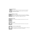
Instructions This symbol is intended to alert the user to the presence of important operating and maintenance (servicing) instructions in the literature accompanying the appliance. Dangerous Voltage This symbol is intended to alert the user to the presence of uninsulated dangerous voltage within the product’s enclosure that may be of sufficient magnitude to constitute a risk of electric shock to persons. Power On This symbol indicates the principal on/off switch is in the on position.
iii TABLE OF CONTENTS Table of Contents Chapter 1: Installation...............................................................1 Introduction.............................................................................................1 Getting Started ........................................................................................1 Installation ..............................................................................................2 Rack Mounting Your Integrated LCD KVM Switch................
iv Integrated LCD KVM Switch Installer/User Guide
1 CHAPTER Installation 1 Introduction Supporting both USB and PS/2 interfaces, the Integrated LCD KVM Switch can control up to eight servers. Built-in keyboard, video and mouse (KVM) peripherals not only save valuable cabinet space, but also enable direct channel selection via on-screen display (OSD) or keyboard hotkeys. The Integrated LCD KVM Switch also features the capacity to daisy-chain up to 16 levels.
2 Integrated LCD KVM Switch Installer/User Guide Installation If you are installing your Integrated LCD KVM Switch to a PS/2 interface, you must turn off all servers before connecting your appliance to a server for proper installation. USB interfaces do not need to be turned off before installation. NOTE: Linux users may experience mouse failure if hot-plugging directly to the Integrated LCD KVM Switch.
Chapter 1: Installation 3 Rack Mounting Your Integrated LCD KVM Switch Your Integrated LCD KVM Switch may be rack mounted using brackets. Before installing the switch, stabilize the rack in a permanent location. Be sure to rack your Integrated LCD KVM Switch in an area of the cabinet that will allow you to utilize the LCD monitor, keyboard and mouse funtions.
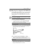
4 Integrated LCD KVM Switch Installer/User Guide 5. Using the flat screws provided, attach both the left and right brackets to the Integrated LCD KVM Switch to secure the unit. Rail Lock Switch Figure 1.3: Utilizing the Rail Lock Switch NOTE: To attach the long support brackets (for cabinet mounts more than 33 inches long), you must remove the factory installed rear brackets and replace with the long brackets provided.
Chapter 1: Installation 5 Accessing and using the OSD menus (LCD monitor) The panel controls listed in the following table allow you to access and manipulate the OSD functions of your LCD monitor (Input Source, Auto Tune, Brightness, Contrast, Color, Position, Language, Recall and Exit). Each LCD monitor OSD function is accessed by pressing the Menu button twice and moving up or down to your selection. Press Menu again to select the option you want to change.
6 Integrated LCD KVM Switch Installer/User Guide Table 1.3: Navigating the OSD Menu (KVM Switch) (Continued) To do this: Use this hotkey sequence: Change Value Left/right arrow keys Select Item Up/down arrow keys NOTE: The two consecutive ScrLk keystrokes should be pressed within two seconds and the following command key(s) should also be pressed within two seconds. Otherwise, the hotkey sequence will not be validated. Figure 1.
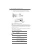
Chapter 1: Installation Figure 1.5: Setup Options Window The following options will be selectable via the Setup OSD window. Table 1.5: Setup Menu Functions Function Description Auto logout Specifies time for auto logout (0 to 99 min). Your password must be configured and enabled for auto logout to function. OSD timeout Specifies duration for OSD menu to remain on screen. Autoscan period Specifies time for the autoscan period. Title bar Specifies the position of the OSD title bar.
8 Integrated LCD KVM Switch Installer/User Guide To upgrade your Integrated LCD KVM Switch: Prior to beginning the firmware upgrade process, ensure that you have an RS-232 port (COM port), a mouse and a keyboard directly connected to the host server. You will also need the upgrade cable, upgrade utility and upgrade file. NOTE: When enabling the upgrade mode via the OSD, be sure to connect a monitor directly to the host server that performs the upgrade. 1. Turn on the Integrated LCD KVM Switch. 2.
Chapter 1: Installation 9 NOTE: During the upgrade process, do not remove the upgrade cable or Integrated LCD KVM Switch power adaptor. 8. An Upgrade complete! message appears above the progress bar after a successful firmware upgrade. You may now exit the utility. Daisy-chaining your Integrated LCD KVM Switch The Integrated LCD KVM Switch features up to 16 levels of attached switches via the daisy-chain cable. The KVM switch has a 128 server daisy-chain limit.
10 Integrated LCD KVM Switch Installer/User Guide
11 APPENDICES Appendices Appendix A: Quick Reference Guide Table A.1: Integrated LCD KVM Switch Quick Reference Guide Command Hotkeys OSD Control Front-panel Description Select Server ScrLk + ScrLk + (a) + (b) + (y) + (z) ab = bank no. xy = channel no.
12 Integrated LCD KVM Switch Installer/User Guide Table A.
Integrated LCD KVM Switch For Technical Support: www.avocent.com/support Installer/User Guide Avocent Corporation 4991 Corporate Drive Huntsville, AL 35805-6201 USA Tel: +1 256 430 4000 Fax: +1 256 430 4031 Avocent International Ltd.