USING THE UNIT SAFELY Before using this unit, please read below warning and precautions which provide important information concerning the proper operation of the unit. Besides, to assure that you have gained a good grasp of every feature of your new unit, read below manual of PVS0615 video switcher. This manual should be saved and kept on hand for further convenient reference. Warning And Cautions ※ To avoid falling or damage, please do not place this unit on an unstable cart, stand, or table.
CONTENT 1.Brief Introduction............................................................................................................................................. 1 1.1 Overview................................................................................................................................................... 1 1.2 Main Features.......................................................................................................................................... 1 2. Connections......
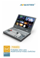
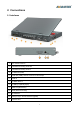
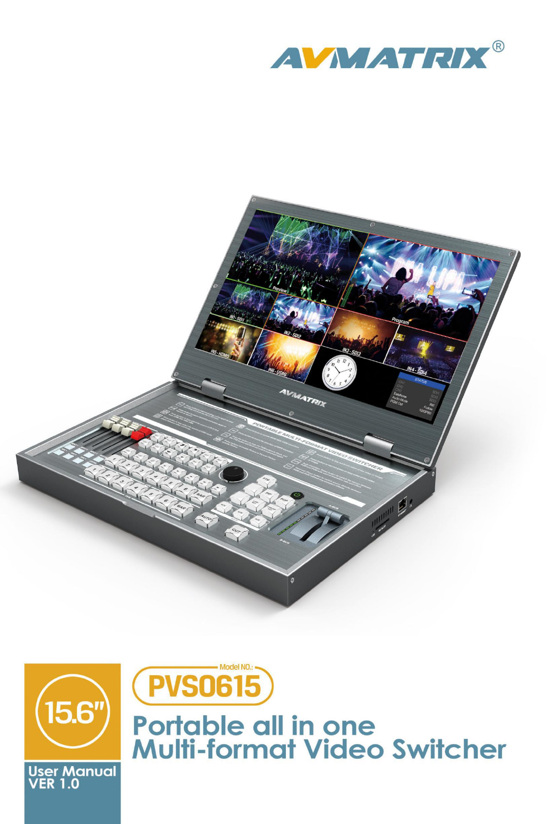
1.Brief Introduction 1.1 Overview PVS0615 is an all-in-one 6-channel video switcher that allows video switching, audio mixing, and video recording. The unit integrated a 15.6” LCD monitor which can be used in wide variety of venues for events, seminars, etc. 1.2 Main Features Portable All-In-One design with 15.
2. Connections 2.
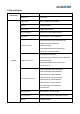
2.2 Specification LCD Display Size 15.6 inch Resolution 1920×1080 Video Inputs SDI×4, HDMI/DVI/VGA/USB×2 Bit Rate 270Mbps~3Gbps Return Loss >15dB, 5MHz~3GHz Signal Amplitude 800mV±10% (SDI/HDMI/DVI/VGA) Impedance 75Ω (SDI/VGA), 100Ω (HDMI/DVI) 1080p 60/59.94/50/30/29.97/25/24/23.98 1080psF 30/29.97/25/24/23.98 SDI Input Format 1080i 60/59.94/50 720p 60/59.94/50/30/29.97/25/24/23.98 625i 50 PAL, 525i 59.94 NTSC 4K 60/50/30, 2K 60/50/30 1080p 60/59.94/50/30/29.97/25/24/23.98/23.
SDI: YUV 4:2:2, 10-bit; Color Space and Precision HDMI: RGB 444 8/10/12bit; YUV 444 8/10/12bit; YUV 422 8/10/12bit PGM Outputs PGM Output Format Outputs Audio Others Accessories 3×HD/3G-SDI; 2×HDMI Type A 1080p 50/60/30/25/24 1080i 50/60 Multiview Output 1×HDMI Type A Multiview Output Format 1080p 60 Return Loss >15dB 5MHz~3GHz Signal Amplitude 800mV±10% (SDI/HDMI/DVI/VGA) Impedance SDI: 75Ω; HDMI: 100Ω DC Offset 0V±0.5V Audio Input 1×TRS(L/R), 50 Ω Audio Output 1×TRS(L/R), 50 Ω; 3.
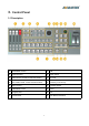
3. Control Panel 3.
3.2 Keyboard Button Audio Mixer Press CH1/ CH2/ CH3 button to select the channel for audio mixing. Press SRC 1/SRC 2/SRC 3 button to select the audio source Master for adjust the main mixing audio to Program. The faders are for adjusting the audio volume. LISTEN button for earphone source selection. Record Control Press REC button to start the video recording. Press REC button again to stop recording. Press PAUSE button to pause the recording process and press it again to continue.
USB Media Player Control Press USB 5/ USB 6 button to select the one which you want to manage. VIDEO/IMAGE buttons is for switching the media format between video and image. The default setting is video. There are Play/Pause, Fast Forward, Fast Backward, BACK and NEXT buttons for USB media control. PGM and PVW PGM row is for selecting the signal source for Program. Selected PGM button will turn on to red LED. PVW row is for selecting the signal source for Preview.
Luma Key Luma Key consists of one video source containing the video image that will be stacked on top of the background. All of the black areas defined by the luminance in the video signal will be made transparent so that the background can be revealed underneath. So, the final composition does not retain any black from the graphic because all of the black parts have been cut out of the image.
4. Operation Instruction 4.1 Multiview Output Layout 1) PGM and PVW as Preview and Program displayed as following image. The level meter of PGM audio is shown only in multiview. SDI/HDMI PGM out is without any overlays. 2) The following 6 windows come from the 6 input signals. The signal source of window 5 and 6 can be selected from HDMI, DVI, VGA, USB. 3) The lower right corner displays the menu and status information. The CH1, CH2, CH3 are the channel selection of the 3 audio sources for audio mixer.
1) Power off the video switcher and press button 1 and 2 of PVW at same time. KEEP pressing the buttons until all calibration process finish. 2) Turn on the video switcher, then the LED indicators will be turn on from bottom to top. 3) Adjust the T-Bar to A-BUS or B-BUS until all LED indicators turn on. Below image is an example of the LED indicators status when switching the T-Bar from B-BUS to A-BUS. 4) Then the T-Bar calibration is finished, and you can release the button 1 and 2. 4.
For example, switching the PGM source to SDI 1 and PVW source to SDI 2. The button selection as below. The default sources of PVW and PGM are SDI 1 and SDI 2 when the first turn the video switch on. When operating the AUTO or T-Bar transition, the selection from PGM row and PVW row is invalid, both of the LED will turn red. 4.3.2 Tally Output PVS0615 is equipped with a 25-pin GPIO interface for tally, the pin outputs are defined as follows: Note: 1.
4.3.3 Transition Control There are two transition control types for this video switcher: Transition without effects and Transition with effects. 1) Transition without Effects CUT performs a simple immediate switch between Preview and Program views. This is no delay seamless switching and the selected transition effect WIPE, MIX or FADE is not used. 2) Transition with Effects AUTO performs an automated switch between Preview and Program views. The timing of the transition is set by the chosen speed button.
Setup the video source of channel 5 or 6 to USB as point 4.3.4, then manage the USB media play from the control panel. Press USB5 or USB6 button to select the one which you want to manage. The VIDEO/IMAGE button is for switching the media format between video and picture. The default setting is video format when the video switcher power on. There are Play/Pause, Fast Forward, Fast Backward, NEXT and BACK buttons to control the media source from USB.
4.5 Audio Mixer Setting 4.5.1 Audio Description This video switcher is coming with 1 channel L/R analog audio input & output and SDI embedded audio. 4.5.2 Audio Mode 1) Mixing Mode Rotary and press the knob button to set audio mode as mixing. Press CH1/CH2/CH3 button to enable the mixing audio mode, total 3 channels for mixing. Press SRC 1/ SRC 2/ SRC 3 buttons to select the audio source from SDI1/ SDI2/ SDI3/ SDI4/ IN5 / IN6/ TRS IN.
4.6 Transition Effects 4.6.1 MIX Transition Pressing the MIX button selects a basic A/B Dissolve for the next transition. When button LED turns on it is active. Then use T-Bar or AUTO to operate the transition. The MIX transition effect as below 4.5.2 WIPE Transition WIPE is a transition from one source to another and is achieved by replacing the current source by another source. Press the WIPE button and the LED turns on then it is active.
4.6.4 PIP and POP When the T-Bar located at B-BUS to active the PIP/POP, there will be a small image display on the top left corner of the PVW window as following image: Press button 1-6 from PVW row to switch the video source of PIP/POP. When press PIP/POP button the menu will enter into an interface as below image. The window size, position and border of PIP can be set from menu by the knob. 4.6.
2) When you press Luma key button, indicator turns on and menu enter into the key setting interface as below image. The color gamut of the Luma Key can be set from the menu by the knob. 4.6.6 Chroma Key Turn on the Chroma Key, a color from the key source will be removed, revealing another background image behind it. Chroma Key is usually used for virtual studio, such as weather broadcasts, where the meteorologist appears to be standing in front of a large map.
4.7 Video Record 4.7.1 Basic Specification Record Video Source PGM Record Storage SD Card (class 10) SD Card Format Max 64GB (file system format exFAT/ FAT32) Record Video Format H.264 (mp4) Record Video Resolution 1080p 60/50/30/25/24hz, 1080i 60/50hz 4.7.2 SD Card Install and Uninstall 1) Install SD card: First, format SD card to exFAT/ FAT32 file system format. Install Plug and press the SD card into the slot from the side of video switcher. Wait 3 sec, the LED indicator beside it will turn on.
Note: 1. The record file will be saved to SD card only after pressing the REC button to stop recording. Otherwise, the record file might be corruption. 2. In case the switcher is power off during record, the record file might be corruption. 3. If you want to change the PGM output resolution during recording, please stop recording and save the file first, then new record the video in new resolution. Otherwise, the record video files in SD card will be abnormal. 4.7.
5.1 System Settings 5.1.1 Language Entering system settings from the menu to switch the system language between English and Chinese. 5.1.2 Clock Entering system settings from the menu to switch the real-time clock shown in Analog or Digital. 5.1.3 Clock Time Setting Connect video switcher to a PC and download a time control software from AVMATRIX official website www.avmatrix.
5.2.2 NetMask Set the NetMask. The default setting is 255.255.255.0. 5.2.3 GateWay Set the GateWay according to current IP address. Save the configuration when network setting finish. 5.3 Record Settings Refer to 4.7.