
User's Manual
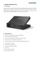
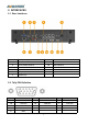
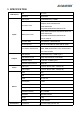
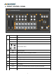
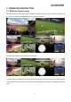
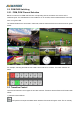
Table Of Contents
- 1.BRIEF INTRODUCTION
- 1.1.Overview
- 1.2.Main Features
- 2.INTERFACES
- 2.1.Rear Interfaces
- 2.2.Tally PIN Definition
- 3.SPECIFICATION
- 4.FRONT CONTROL PANEL
- 5.OPERATION INSTRUCTION
- 5.1.Multiview Output Layout
- 5.2.PGM PVW Switching
- 5.2.1.PGM, PVW Channel Selection
- 5.3.Transition Control
- 5.3.1.FTB (Fade to Black)
- 5.4.Audio Mixer Setting
- 5.4.1.Audio Description
- 5.5.Transition Effects
- 5.5.1.MIX Transition
- 5.5.2.WIPE Transition
- 5.5.3.FADE Transition
- 6.MENU SETTING
- 6.1.SDI PGM/ AUX and Multiview Output Format
- 6.2.Audio Setting
- 6.2.1.Mixing Mode
- 6.2.2.AFV Mode
- 6.3.PIP Mode
- 6.4.Main Menu Setting
- 6.4.1.System Settings
- 6.5.Network Settings
- 6.5.1.Network
- 6.5.2.NetMask
- 6.5.3.GateWay

6
5. OPERATION INSTRUCTION
5.1. Multiview Output Layout
PGM and PVW as Preview and Program displayed as following image. The level meter of PGM audio is
shown only in multiview. SDI/HDMI PGM out is without any overlays.
The following 6 windows come from the 6 input signals.
The lower right corner display of the menu and status information.The CH1,CH2 are the channel selection
of the 2 audio sources for audio mixer.There is a real-time Digital clock/Analog clock displayed beside the
menu.