
User's Manual
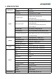
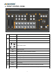
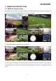
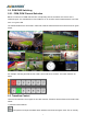
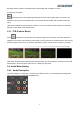
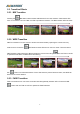
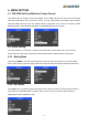
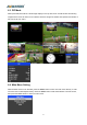
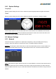
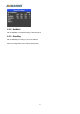
Table Of Contents
- 1.BRIEF INTRODUCTION
- 1.1.Overview
- 1.2.Main Features
- 2.INTERFACES
- 2.1.Rear Interfaces
- 2.2.Tally PIN Definition
- 3.SPECIFICATION
- 4.FRONT CONTROL PANEL
- 5.OPERATION INSTRUCTION
- 5.1.Multiview Output Layout
- 5.2.PGM PVW Switching
- 5.2.1.PGM, PVW Channel Selection
- 5.3.Transition Control
- 5.3.1.FTB (Fade to Black)
- 5.4.Audio Mixer Setting
- 5.4.1.Audio Description
- 5.5.Transition Effects
- 5.5.1.MIX Transition
- 5.5.2.WIPE Transition
- 5.5.3.FADE Transition
- 6.MENU SETTING
- 6.1.SDI PGM/ AUX and Multiview Output Format
- 6.2.Audio Setting
- 6.2.1.Mixing Mode
- 6.2.2.AFV Mode
- 6.3.PIP Mode
- 6.4.Main Menu Setting
- 6.4.1.System Settings
- 6.5.Network Settings
- 6.5.1.Network
- 6.5.2.NetMask
- 6.5.3.GateWay

12
6.4.1. System Settings
Language
Entering system settings from the menu to switch the system language between English and Chinese.
Clock
Entering system settings from the menu to switch the real-time clock shown in Analog or Digital.
Connect video switcher to a PC and download a time control software from AVMATRIX official website
www.avmatrix.net/download/ Open the software and click Scan to search and connect the device, then
the clock time will be changed to same time to the PC’s time.
6.5. Network Settings
6.5.1. Network
There are two ways to acquire the IP: Dynamic(IP configured by router) and Static(set IP freely by
yourself) . Select the method you need by knob menu. The default setting is Daynamic.
Dynamic: Connecting the video switcher with a router with DHCP features, then it will auto obtain an IP
address automatically. Make sure that the video switcher and PC are in the same local area network.
Static: Select static IP acquire method when the PC is without DHCP. Connect the video switcher with PC
via network cable,set the PC’s IP address to the same IP range as video switcher( the video switcher’s
default IP address 192.168.1.215), or set the video switcher’s IP address to the same IP range as PC’s IP
address.