AVIOS 1450MM SUPERMARINE SPITFIRE Mkvb INSTRUCTION MANUAL
SAFETY INSTRUCTIONS 1. Please read this manual carefully and follow the instructions before you use this products. 2. Our airplane is not a toy, it is only suitable for experienced pilots. If you are a novice then please only fly under the guidance of an experienced pilot. 3. Not recommended for children under 14 years old. 4.
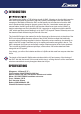
INTRODUCTION The Supermarine Spitfire is THE defining aircraft of WW2, following on from the Mk1a was the Mk5 which represents the pinnacle of the early Sptifire's development. After the defensive campaign of the Battle of Britain the RAF moved steadily into an offensive roll and the Mk5 was to spearhead this change in the early years of the war. It was better armed and more manoeuvrable, the Mk5 gave the RAF and the other Allied forces (such as the USAAF) a decisive advantage over the Luftwaffe's Bf 109.
REQUIRED TO COMPLETE MODEL: In its "Plug N Fly" format the Spitfire Mk5 will still require some additional electronic components to get it "flight ready". Avios recommends the following products for optimum performance and great value. All these items are available at HobbyKing.com . Transmitter: OrangeRx TX6i 2.
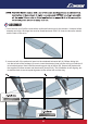
ASSEMBLY 1. Out of the box your Spitfire comes with a reinforced foam hinge for the elevator. However before assmbly can begin, the hinge line must be flexed back and forth 5-6 times to reduce the tension and the load on the servo. 2. Insert one half of the carbon tail spar into the starboard horizontal tail (A). Before sliding this into the tail slot of the fuselage, be sure to insert the elevator joiner into the driving unit which will drive both elevators.
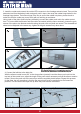
3. Insert the rudder and connect the rudder LED connector to the fuselage extension lead. Then pull the extension lead from the battery hatch end gently until it stops, then snap the rudder hinge halves to the fuselage hinge halves. The bottom hinge is the key to secure the rudder into place, please check to make sure that the rudder can move freely with no catching or resistance. Using a pair of the pliers (ball link pliers preferably) connect the rudder push rod to the rudder control horn.
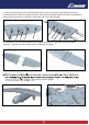
5. Using a small amount of the supplied contact glue, secure the under wing radiators, the servo covers(check the fit first, then glue into place), the cannon magazine blisters (use the 2 small holes to center) and the pitot tube. Insert the 2 main wing spars into one wing half. 6. Connect the 2 wing halves together (we suggest applying a bit glue to the roots for better security). The cannons can also be glued into place at this point. 7 4x16mm bolts supplied.
. We recommend you seal the slot between the wing panels using the supplied plastic strips. If your choice is the ETO, then you can glue the air scoop on, if you have the Desert version please glue the two pieces of the volks filter in to place (be sure not to glue the rear and the front filter part together), then secure the cowl using (2.3x10) screw. 9. Glue into place the fish tail and the exhaust stacks , the fuselage aerial and the rear view mirror. 10.
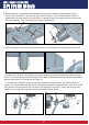
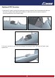
Optional FPV Version: 1. Install the FPV gear by sliding and opening the canopy rearward, then disassemble the head rest, Glue the FPV gear as far rearward as possible, it is also best to remove the wind shield to reduce the distortion of the camera image. 2. You can cover the air vent under the fuselage if the canopy is open, this gives it a better scale appearance.
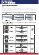
SETTING UP YOUR MODEL: 1.With your receiver installed and the servos plugged into their correct channels you can connect the flight battery to the ESC and power up the electronics. Once the model is armed ensure all the servos are centered correctly and all control surfaces are neutral. If not then adjust the push rod lengths until the control surface is neutral.
30-40mm 30-40mm 80-95mm 10-15mm 10-15mm • Elevator: "Low Rates" 10mm "High Rates" 20mm each direction from neutral. • Rudder: "Low Rates" 30mm "High Rates" 40mm each direction from neutral. • Ailerons: "Low Rates" 10mm "High Rates" 15mm each direction from neutral. The above are recommendations for your first flights. Once you have test flown the model you can adjust to suit your particular flying style. 4. Flaps on the Spitfire should be set for 3 stages (up/no flap, mid flap and full flap).
5. The center of gravity (CofG) for the Spitfire is between 80-95mm from the leading edge of the wing. If you use the recommended "Turnigy Nano-Tech" 3300mah 65C 6S lipoly pack then the forward balance point will be achieved by simply having the battery as far forward as possible. If using a lighter battery then some nose weight will need to be added, if a heavier battery or you prefer a more rearward CofG then slide the battery rearwards in the battery compartment.
MODEL FLYING PRECAUTIONS • Select your flying area carefully. Always choose an open space that is clear of trees and buildings and is away from crowded area's. Avoid flying near roads, electric/telephone poles and wires, water or close to a full size active airfield. • Do not fly the model in poor weather, high winds or low visibility. Rain and storms should also be avoided. • Never attempt to catch the model whilst flying, even a slow moving model can cause injury.
FLYING YOUR SPITFIRE Before flying make sure you have followed closely the set-up guidelines on pages 6 to 9. Start by taxying around a little to get used to the ground handling. Always make sure you use full up elevator when taxying to avoid nosing over and to keep pressure on the tailwheel, keep the flaps up and use the throttle gently. This will keep the model tracking steady and true, plus it has the added bonus of looking more scale like.
SPITFIRE TIPS • For optimum flight performance and model longevity we recommend that you always fly with a balanced propeller. The supplied propeller should be balanced but it is always good practice to check this. • Keep all leads within the fuselage area as tidy as possible.
15
16
DECAL APPLICATION GUIDELINES 17
household Your Spitfire comes with some stickers already applied out of the box. Keep in mind that this model has travelled a long way and has experienced many temperature changes. These occasionally causes the edges of the pre-applied stickers to lift. Use an iron in the same way as you did on the main decals you have applied and this will seal down the decal once more.
DECAL TIPS • Rub the clear front film before you remove the decal from the paper backing to ensure it lifts fully from the backing. • Remove the clear fronting by pulling it gently of to one side once the decal has been applied. DO NOT pull this clear film directly upwards as this could cause the decal to tear. • To avoid bubbles under the larger decals use a sharp blade to remove the small molding marks from the surface of the foam where the decal is to be applied. • Scale "Maintenance" decals found on "p.
04 20
21 04 04
22
04 23
04 24
25
26
27
28
29
30
31
32