Cirrus EXP5000 Primary Flight Display Pilot’s Guide 600-00142-000 Rev 01
Document Revision History Date Revision Description Sept. 30, 2005 00 Released per ECO-05-162 Oct. 14, 2005 01 Updated per ECO-05-179 This document is applicable to Software Part Number 530-00177-000. All materials copyrighted including images that represent this software Copyright 2005 Avidyne Corporation. All rights reserved.
Table of Contents 1 Introduction .............................................................. 1 Notes and Warnings 1 Copyrights and Trademarks 2 AVIDYNE EXCLUSIVE LIMITED WARRANTY/LIMITATIONS ON LIABILITY .................................................................................... 3 2 EXP5000 System Overview ..................................... 5 Entegra EXP5000 Overview 5 EXP5000 Upper Half Display ...................................................... 7 Upper Half Display .....................
4 Invalid Sensors and Error Conditions ................. 41 Invalid Air Data .......................................................................... 42 Invalid Heading.......................................................................... 43 Crosscheck Monitor................................................................... 44 Warmstart Conditions ................................................................ 45 Recoverable Attitude .................................................................
This page intentionally blank.
1 Introduction This Pilot’s Guide provides information about the Entegra EXP5000 PFD for the following aircraft: ● Cirrus SRV ● Cirrus SR20 ● Cirrus SR22 Note: All images contained within this document, including screenshots and other displays, are for reference use only and are subject to change. The images contained herein may differ slightly from your actual equipment or display. 1.1 Notes and Warnings Notes and warnings provide guidance for the use of the EXP5000.
Introduction understanding of the warnings, operating instructions, and limitations for all equipment installed on your aircraft. ! ! This manual assumes that the reader is an appropriately licensed pilot. Avidyne strongly recommends that you use the EXP5000 only under VFR conditions until you are very familiar with the EXP5000. If you have questions, please contact Avidyne at 800-2843963 (800-AVIDYNE) before operating with the Entegra PFD under IFR conditions.
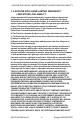
AVIDYNE EXCLUSIVE LIMITED WARRANTY/LIMITATIONS ON LIABILITY 1.3 AVIDYNE EXCLUSIVE LIMITED WARRANTY/ LIMITATIONS ON LIABILITY Avidyne warrants the Product manufactured by it against defects in material and workmanship for a period of twenty-four (24) months from delivery. If Avidyne's Product fails to conform to this warranty, Avidyne, in its sole discretion, will either repair or replace the Product or provide a refund of the purchase price paid for the Product.
Introduction AVIDYNE (OR ITS AFFILIATES) WERE NOTIFIED OF THE POSSIBILITY THAT ANY DAMAGE MIGHT BE INCURRED), ARISING OUT OF OR RELATED TO THE PRODUCT, ITS PURCHASE OR SALE, ITS PERFORMANCE OR RELIABILITY, OR THE USE OR INABILITY TO USE THE PRODUCT, FOR ANY REASON, INCLUDING DUE TO ANY PRODUCT DEFECT OR DEFECTS OR ANY ACTION OR INACTION OF ANY NATURE (INCLUDING CLAIMED OR ACTUAL NEGLIGENCE OR GROSS NEGLIGENCE) BY AVIDYNE OR ANY SUPPLIERS OF PRODUCT COMPONENTS.
2 EXP5000 System Overview This section contains the following information: ● Entegra EXP5000 Overview, page 5 ● EXP5000 Upper Half Display, page 7 ● EXP5000 Lower Half Display, page 12 ● EXP5000 Buttons and Knobs, page 15 2.1 Entegra EXP5000 Overview This section provides an overview of the Entegra EXP5000 window. 1 2 3 3 4 5 5 6 6 Figure 1. The Entegra EXP5000 PFD 1) Brightness Control (BRT/DIM)—Allows you to adjust the display brightness.
EXP5000 System Overview 2) Upper Half Display—The upper half of your EXP5000 window displays information about your power plant, aircraft attitude, autopilot status (when equipped), navigation and more. This section includes the following: ■ Engine instruments ■ Autopilot annunciations ■ Attitude Direction Indicator (ADI) ■ Airspeed Indicator (ASI) ■ Altimeter ■ Vertical Speed Indicator (VSI) For information about the data displayed on the upper section of the EXP5000 window, see Section 2.
EXP5000 Upper Half Display 2.2 EXP5000 Upper Half Display 3 6 1 4 7 12 8 9 2 13 5 10 15 14 11 Figure 2. EXP5000 Upper Half Display Symbols Upper Half Display The upper portion of the EXP5000 contains the following information: 1) M-BUS and E-BUS Data Block—Indicates Main and Essential Bus voltages. The pop-up display allows you to check battery voltages prior to engine start.
EXP5000 System Overview 2) %Power Tape—Indicates the calculated percent of maximum rated power currently being produced by the engine. Percent Power is calculated by the EXP5000 based on engine RPM, manifold pressure, pressure altitude, outside air temperature, and fuel flow. If your aircraft is not configured for Primary Engines, the M-BUS and E-BUS data blocks and the % Power tape will not display. 3) Autopilot Annunciation Area—Displays the autopilot annunciations in your primary field of view.
EXP5000 Upper Half Display 7) Skid/Slip Indicator—The black trapezoid is centered under the roll pointer in coordinated flight. Full scale deflection is the width of the trapezoid. 8) Pitch Ladder—The pitch ladder is marked as follows: ■ Every 2 1/2° within the range of ± 20°. ■ Every 5° from +20° to +50° and -20° to -30°. ■ 10° graduations of the pitch ladder have bar ends that point toward the horizon line. ■ ±90° is represented by small circles.
EXP5000 System Overview 11) Horizontal Deviation Indicator (HDI)—Displays when: ■ The NAV source is VLOC. ■ The localizer signal has been received. The source of the HDI data is displayed immediately to the right of the HDI (e.g. LOC or ILS). If the signal is lost, the HDI is replaced with a red X and the source letters turn red. To remove the HDI, change either the NAV source or the VOR/ LOC frequency.
EXP5000 Upper Half Display E, S, W) and mid-quadrant (NE, SE, SW, NW). The reference pointer for the Heading Marks is the apex of the ARS. Labeled VSpeeds Under high power conditions, the Vx and VY labels are shown at the correct airspeeds for the Best Angle of Climb speed (VX) and Best Rate of Climb speed (VY). VX and VY are adjusted based on density altitude, as described in the Airspeeds for Normal Operations section of your aircraft Pilot Operating Handbook.
EXP5000 System Overview 2.3 EXP5000 Lower Half Display The lower half of your EXP5000 provides the Horizontal Situation Indicator (HSI) function and other information. You can choose to display the HSI as either a full 360° circle or as a 120° arc. The arc view is shown in Figure 4 on page 14. ➥ All features can display in both the 360° and 120° views. 1 2 3 5 4 6 8 7 9 11 12 10 Figure 3. EHSI 360° View 1) Magnetic Heading—A numeric indication of current aircraft magnetic heading.
EXP5000 Lower Half Display The wind vector on the HSI is very useful in any phase of flight where you need to take winds aloft into account. You can use a combination of the wind vector and projected track line in navigation tasks. Note: Under very light wind conditions or when wind speed cannot be calculated, wind data will be replaced by dashes.
EXP5000 System Overview in nautical miles. Outer ring ranges are 2, 5, 10, 20, 50, 100, and 200 NM. 10) Compass Rose—In both the 360° view and 120° arc view, the minor graduation marks represent 5 degrees, major graduation marks represent 10 degrees, with every 30 degrees labeled. The outer edge of the compass rose is marked with reference marks.
EXP5000 Buttons and Knobs 2.4 EXP5000 Buttons and Knobs Left Buttons and Knob The left-hand buttons and knob on the Entegra EXP5000 allow you to set the navigation configuration and course. The Nav (Primary Navigation) button is enabled by default (the enabled button has a green rim). To enable a different left-hand button, press it. Once enabled, you can continue to press the button to change the setting.
EXP5000 System Overview 2) Bearing (Secondary Navigation)—Controls the source for the Bearing Pointer and adjacent data block. In a dual GPS/VHF navigator system, the available sources are: GPS 1, VLOC 1, GPS 2, VLOC 2, ADF (if available), OFF. 3) Aux (Auxiliary Navigation)—Controls the source of the adjacent data block only. In a dual GPS/VHF navigator system, the available sources are: GPS 1, VLOC 1, GPS 2, VLOC 2, ADF (if available), OFF.
EXP5000 Buttons and Knobs 5) Left Knob—The function of the left knob changes depending on the enabled button. ■ When Nav is enabled, the Crs Set label displays when you can set a course, as shown in Table 2.1. For information about setting a course, see Section 3.5, "Using GPS/VHF Systems with the EXP5000" on page 29. Table 2.
EXP5000 System Overview The Bearing and Aux data block content depends on the source, as follows: Table 2.
EXP5000 Buttons and Knobs Right Buttons and Knob After you press a button to enable it, use the right knob to change the target settings for that Bug (or setting). The knob label displays the current functionality, as shown in Table 2.5 on page 21. Note: The Hdg Bug button is re-enabled ten seconds after you last push or rotate the knob to set the Alt Bug, VSI Bug, or Baro Set buttons. Avidyne recommends that you always select the desired button just before you use the knob.
EXP5000 System Overview 2) Heading Bug (Hdg Bug)— Controlled by the right knob when Hdg Bug is selected, the notched part of the magenta bug symbol indicates the current Heading Bug value. The Heading Bug is positioned on the selected side of the compass rose and remains in partial view when the HSI is in 120° view and the Heading Bug value is outside the current compass rose field of view. The range is 001 to 360 degrees. 3)Altitude Bug (Alt Bug)— Controlled by the right knob when you select Alt Bug.
EXP5000 Buttons and Knobs VSI Bug set value. The VSI Bug displays on the VSI Indicator. The VSI Bug range is ±1,600 fpm, which is the maximum vertical speed allowed by the S-TEC 55X autopilot. 6) Barometric Correction Setting (Baro Set)—Controlled by the right knob when you select Baro Set, the value indicates the current barometric correction setting. The baro correction may display as inches of mercury (Hg), millibars (Mb), or hectopascals (Hp). Barometric units are set during EXP5000 installation.
3 Flying with the EXP5000 3.1 Introduction This chapter contains all the basic information you need to use the EXP5000.
Starting the EXP5000 3.2 Starting the EXP5000 The EXP5000 includes a solid state Air Data and Attitude Heading Reference System (ADAHRS) which requires an alignment time before you are ready for flight. The EXP5000 is designed to operate during engine start and shut down procedures. EXP5000 start-up is automatic once power is applied via the battery switch. ➥ A common startup procedure is to turn on BAT and conduct the aircraft preflight during the ADAHRS alignment process.
Flying with the EXP5000 EXP5000 Alignment Messages Note: For faster alignments (3 minutes or less), Avidyne recommends that you do not move the aircraft until alignment is complete. The OK TO TAXI message provides increased flexibility during ground operations, but it may extend overall alignment time. Table 3.
Starting the EXP5000 AHRS Alignment Errors While alignment and startup should proceed smoothly, in the case of error, you may see one of the following messages in the AHRS Init box: Table 3.7 AHRS Alignment Errors Message Recommended Pilot Action UNABLE TO COMPLETE ALIGNMENT Stop aircraft as soon as practical and wait for alignment to resume. MOTION SENSED - STOP AIRCRAFT Alignment Should Resume Within 2 Mins. UNABLE TO COMPLETE ALIGNMENT Move Aircraft to different location and begin startup operations.
Flying with the EXP5000 3.3 Startup Settings Figure 8.
Setting Up the HSI 3.4 Setting Up the HSI The Entegra EXP5000 can integrate with single or dual GNS 400/ 500-series GPS or GPS/VHF navigator systems. When your EXP5000 PFD is installed, it is configured for the number and type of navigator systems on board. Use the Nav button (Primary Nav) to select the navigator source for the green single-line CDI and the moving map data.
Flying with the EXP5000 For information about loading data into your GPS/VHF unit see the Pilot’s Guide for your GPS/VHF system. Note: The CDI on the EXP5000’s HSI comes from the selected Nav source which may be different from the CDI displayed on the GPS 1 or GPS 2 displays.
Using GPS/VHF Systems with the EXP5000 3.5 Using GPS/VHF Systems with the EXP5000 You can use the EXP5000 to set a primary navigation course setting on the HSI when one of three conditions is met: ● PFD Nav Source = GPS 1 or GPS 2 and the selected GPS/VHF system is in OBS mode. ● PFD Nav Source = VLOC 1 or VLOC 2 and the current frequency is a VOR station. ● PFD Nav Source = VLOC 1 or VLOC 2 and the current frequency is an ILS or localizer. In this case, you can set a course for reference.
Flying with the EXP5000 3.6 Controlling the Autopilot Your Entegra EXP5000 is integrated with the S-TEC Fifty Five X (55X) or S-TEC 55SR Autopilot. When you select an active autopilot mode, full guidance is provided from the EXP5000 to the autopilot, including heading captures and, for the S-TEC 55X only, smooth transitions to altitude. The status of the reference Bugs, autopilot annunciations, and Flight Director steering command bars indicate when the EXP5000 is coupled with the autopilot.
Controlling the Autopilot will become solid magenta and the autopilot will track the input heading. The autopilot control head and the EXP5000 will indicate “HDG”. The Heading Bug will remain solid magenta until heading mode is cancelled. Select a new heading at any time while the autopilot is in heading mode and the autopilot will track the new Heading Bug value. Nav Mode Press the NAV button on the autopilot control head to engage Nav mode. The autopilot will intercept and track the desired course.
Flying with the EXP5000 ! If a VLOC is selected in NAV on the PFD and GPSS mode is engaged on the autopilot, the autopilot will track the active flight plan in GPS 1 if VLOC 1 is selected or GPS 2 if VLOC 2 is selected. It will not track VLOC 1 or VLOC 2 as the selected source in NAV on the PFD. Therefore the course deviation on the PFD CDI and the course deviation flown by the autopilot can be different. This situation may be confusing and should be avoided.
Controlling the Autopilot Altitude Capture Mode (S-TEC 55X only) Push the Alt Bug button on the EXP5000 and rotate the right knob on the EXP5000 to set a desired target altitude. Engage Altitude Capture mode by simultaneously pressing the ALT and VS buttons on the autopilot control head. The Alt Bug and VSI Bug will become solid magenta, while the Flight Director steering command bars, if configured on the aircraft, are shifted to correspond with the autopilot commands.
Flying with the EXP5000 The color of the Flight Director steering command bars reflect the status of the autopilot, as follows: ● When the autopilot is in AP mode, the Flight Director steering command bars are magenta. In AP mode, the autopilot steers the airplane toward the command bars until the Aircraft Reference Symbol (ARS) is tucked into the steering command bars. ● When the autopilot is in FD mode, the Flight Director steering command bars are green.
Precision Flying with EXP5000 3.7 Precision Flying with EXP5000 This section describes several techniques which take advantage of the EXP5000’s features to produce precision flight performance. Obtaining Level Flight You can obtain level flight by placing the apex of the yellow deltashaped reference symbol on the horizon line in cruise conditions of 6000’ MSL at 160 KIAS. The pitch angle for level flight will vary with flight conditions, depending on speed, altitude and weight.
Flying with the EXP5000 Using Trend Indicators Use the trend indicators to capture and maintain a desired airspeed and altitude by adjusting the pitch and/or power to the airspeed or altitude you want. This results in a smooth capture of the desired airspeed and altitude. 1 4 2 3 Figure 10. Trend Indicators 1) Airspeed Trend Indicator—The tip of the blue airspeed trend indicator displays the predicted airspeed six seconds into the future at the current rate of change.
Precision Flying with EXP5000 4) Altitude Trend Indicator—The tip of the blue airspeed trend indicator displays the predicted altitude six seconds into the future at the current rate of change. An arrowhead indicates a value beyond the current tape field of view.
Flying with the EXP5000 3.8 Using the EXP5000 for Approaches Precision Approaches Figure 11. Flying an ILS Approach Flying an ILS Approach The EXP5000 is designed to take full advantage of the auto transition capability of the Navigator systems for flying a GPS flight plan ending in an ILS approach. In this case, the horizontal deviation indicator (HDI) and vertical deviation indicator (VDI) windows are displayed on the ADI.
Using the EXP5000 for Approaches Flying an Autopilot-Coupled Approach (S-TEC 55X Only) To perform an autopilot-coupled approach, ensure the approach has been activated in the Navigator selected as the Nav source. Then: ● Press NAV on the autopilot control head to activate Nav mode. ● Press the APR button on the Autopilot control head to activate the Glideslope capture capability. The autopilot will then track the Glidescope and localizer.
Flying with the EXP5000 ■ Use the EXP5000 Alt Bug to set the desired intermediate level off altitude or the minimum descent altitude (MDA) as a visual reminder. 3) After crossing the FAF, select VS mode on the autopilot. 4) Just prior to reaching MDA, select ALT on the autopilot to command altitude hold. Flying a Back Course Localizer Approach The EXP5000 is designed to fully support flying back course localizer approaches.
4 Invalid Sensors and Error Conditions When the data coming into the EXP5000 is unavailable or otherwise invalid, the EXP5000 provides appropriate warnings and messages.
Invalid Sensors and Error Conditions 4.1 Invalid Air Data Figure 12. Invalid Air Data If air data becomes unavailable: 1) Airspeed, altitude, and vertical speed data are removed and replaced by red X’s. 2) Wind Vector data is removed and replaced by dashes. 3) Outside Air Temperature and True airspeed data are removed and replaced by dashes. 4) The % Power ape is removed. If invalid air data occurs: ● Use the mechanical backup airspeed indicator and altimeter.
Invalid Heading 4.2 Invalid Heading Figure 13. Invalid Heading If valid heading data becomes unavailable, heading data and HSI navigation data are removed from the display and replaced with a red X. Note: Refer to the aircraft compass for heading. Refer to the EX5000 MFD or GPS Navigator for ground track and flight plan. When heading data is determined to be valid, the display of heading and HSI navigation data will be restored.
Invalid Sensors and Error Conditions 4.3 Crosscheck Monitor Figure 14. Crosscheck Monitor The Entegra EXP5000 comes equipped with a self-check monitor. When this monitor detects a condition that does not warrant removal of data, a CROSSCHECK ATTITUDE warning message displays. When this message is displayed, scan all backup instruments and auxiliary instruments (backup attitude indicator, backup airspeed indicator, and back up altimeter) to crosscheck the aircraft attitude.
Warmstart Conditions 4.4 Warmstart Conditions The EXP5000 is capable of performing a warmstart from a fully aligned condition when subjected to a power loss of less than 30 seconds. In this event, the “PLEASE STANDBY” message in the warmup box is displayed for approximately 2 seconds followed by the “ATTEMPTING QUICK RESTART” message and its countdown. There is no requirement to limit dynamic maneuvering during this warmstart attempt.
Invalid Sensors and Error Conditions 4.5 Recoverable Attitude Figure 16. Recoverable Attitude Situation If a recoverable attitude data failure occurs: 1) All normal button labels are removed. 2) Attitude data is removed from the display and replaced with a red X. 3) A Fast Erect button label and message displays. When you press Fast Erect, the message will change to “Maintain straight and level flight” until the 10 second count-down timer expires. At that point, all attitude data is restored.
Invalid Attitude & Heading 4.6 Invalid Attitude & Heading Figure 17. Invalid Attitude and Heading If valid attitude and heading data becomes unavailable, attitude data, wind vector data, heading data, and HSI navigation data are removed from the display. Note: You may be able to recover from a failed attitude condition by pulling both PFD circuit breakers for less than 20 seconds. This will initiate a warmstart as described in Section 4.4, "Warmstart Conditions" on page 45.
Invalid Sensors and Error Conditions 4.7 Invalid Engine Data Figure 18. Invalid Engine Data If valid engine data becomes unavailable: 1) %Power tape will be removed from the display. 2) Engine Instrument numeric readouts will be shown as white dashes instead of digits. ! It is likely that if data for one engine instrument is lost, that data will be lost for all engine instruments. Use engine instruments on the Multi-Function Display (MFD).
Nav Source Crosscheck 4.8 Nav Source Crosscheck When receiving valid navigation information from two radios tuned to the same navigation aid, the EXP5000 compares the data from the two and provides an alert if there is a miscompare. This comparison is only done when one of the radios is selected as the primary navigation source. Figure 19. Localizer and Glideslope Crosscheck Errors Figure 20.
5 Software License Avidyne Corporation (“Avidyne”) is willing to license this software, pilot's guide, and related materials (the “Software”) only on the condition that you agree to all the terms of this agreement. Please read these terms carefully. Trademarks Avidyne, the Avidyne logo, Entegra, the Entegra Logo, FlightMax, and the FlightMax logo are trademarks of Avidyne Corporation.
Restricted Rights Legend Use, duplication, or disclosure by the Government is subject to restrictions as set forth in subparagraph (c)(1)(ii) of the Rights in Technical Data and Computer Software clause at DFARS 52.227-7013, and when applicable subparagraphs (a) through (d) of the Commercial Computer-Restricted rights clause at FAR 52.227-19, and in similar clauses in the NASA FAR Supplement. - Avidyne Corporation, 55 Old Bedford Road, Lincoln, MA 01773.
AVIDYNE CORPORATION 55 Old Bedford Road Lincoln, MA 01773 Telephone: 781-402-7400 Toll Free: 800-AVIDYNE (800-284-3963) FAX:781-402-7599 www.avidyne.com P/N 600-00142-000 Rev 01 10/05 ©2005 Avidyne Corporation All Rights Reserved. Avidyne®, FlightMax® and CSS™ are trademarks of Avidyne Corp.