
Installation manual


Installation Manual
P/N 600-00175-000 Rev 04 MFD Feature Setup and Checkout
- 49 -
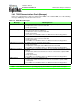
Table 22 describes the beam width selections. For more information see the installation and
operations manuals for your radar system.
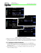
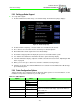
5.9.4 Adjusting the Roll Trim
➤ To adjust the Roll Trim Adjustment:
1. From the Maintenance Mode Page, select Setup Radar.
2. From the Radar Setup page, select Roll Trim.
3. The Roll Trim value appears on the Radar screen and can be modified by the Roll Trim control
knob.
4. When you are done, press Back to save the new Roll Trim setting and return to the Radar Setup
Page.
5. Press Save from the Radar Setup Page. Press Cancel to exit without saving changes.
6. Changes do not take effect until the MFD has been restarted. From the Maintenance Mode Page,
press Restart System.
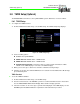
5.9.5 Calibrating the Radar System
Some radar systems require calibration after installation. When you restart the Radar Setup page, an
R/T Calibration button displays if required.
➥ Perform radar R/T calibration according to the procedures and specifications for the specific unit
installed in the aircraft.
You can calibrate the radar after it has been installed, setup and checked out per the radar
manufacturer’s instructions.
Calibrating the Bendix/King RS-181A and RS-8xx Series Radar Sensors
➤ To calibrate the system:
1. From the Maintenance Mode Page, select Setup Radar.
2. From the Radar Setup page, select R/T Calibration.
3. Calibrate the radar following the specifications in the R/T unit's Installation Manual.
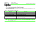
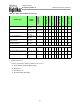
Enable Auto-Tilt Control Checkbox When checked, enables Radar auto-tilt mode.
Primary Indicator (1) Checkbox When checked, enables EX500/EX600 control of radar
functions.
Disable Stabilization Checkbox Disables EX500/EX600 display of the “Stab Off” annunciation
Enable Automatic Standby Checkbox When checked, enables the EX500/EX600 to auto-command
the radar to standby when ground is sensed to be below 20 kts.
ARINC 429 Port — Digital Radar Only
ARINC 453 Port — Digital Radar Only
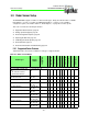
Table 22: Radar Beam Widths
Antenna Width Generic Beam Width Bendix/King Radars Collins Radar
10” 10° 10° 9.5°
12” 8° 8° 8°
18” 5° 5.6° 6°
Table 21: Radar Options (Continued)
Option Value Notes