
Installation manual


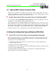
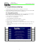
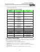
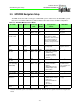

Figure 6: Connecting Heading Source through Synchro Interface
4.9.8 Radar Sensor Wiring
Installation Manual
P/N 600-00175-000 Rev 04 Installation Planning
- 23 -
Configuring Map Heading from a Heading Source using the Synchro Interface
The EX500/EX600 is capable of receiving heading data directly from a heading source using the
Synchro interface as shown in Figure 6. The Synchro pins on the MFD are identified in Table 4 and
Figure 1. Also see Figure 34, “EX500/EX600 General Wiring,” on page 95 for Synchro connection
information.
See Appendix J: Radar Wiring, on page 100 for the appropriate wiring diagram.
Heading Source (Synchro) MFD