EXP5000 Primary Flight Display Pilot’s Guide 600-00157-000 Rev.
Document Revision History Date Revision Description Oct. 12, 2006 00 Oct. 18, 2006 01 Released per ECO-06-230 Released per ECO-06-238 Aug. 8, 2007 02 Updated per ECO-07-254 Oct. 3, 2007 03 Updated per ECO-07-352 May 21, 2008 04 Updated per ECO-08-131 June 27, 2008 05 Updated per ECO-08-199 August 29, 2008 06 Updated per ECO-08-249 This document is applicable to Software Part Numbers: ● 530-00194-000 - Rel 7.0.X, Landscape PFD, No RVSM ● 530-00200-000 - Rel 7.
This page intentionally left blank. Entegra EXP5000 PFD -ii- 600-00157-000 Rev.
Table of Contents 1 Introduction .............................................................. 1 Notes and Warnings .................................................................... 1 2 EXP5000 System Overview ..................................... 3 EXP5000 Overview ..................................................................... 3 EXP5000 Upper Half Display ...................................................... 5 EXP5000 Lower Half Display ....................................................
Copyright....................................................................................75 AVIDYNE EXCLUSIVE LIMITED WARRANTY and LIMITATIONS ON LIABILITY..............................................76 Software License .......................................................................79 Entegra EXP5000 PFD -iv- 600-00157-000 Rev.
1 Introduction This Pilot’s Guide provides information about the Envision EXP5000 PFD. 1.1 Notes and Warnings Notes and warnings provide guidance for the use of the EXP5000. Avidyne strongly suggests that you pay close attention to notes and warnings for your own safety. For example: Note: Notes provide useful information about how to use the EXP5000 Primary Flight Display.
Notes and Warnings This page intentionally left blank. Entegra EXP5000 PFD -2- 600-00157-000 Rev.
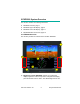
2 EXP5000 System Overview This section contains the following information: ● EXP5000 Overview, page 3 ● EXP5000 Upper Half Display, page 5 ● EXP5000 Lower Half Display, page 11 ● EXP5000 Buttons and Knobs, page 15 2.1 EXP5000 Overview This section provides an overview of the Envision EXP5000. 1 2 3 3 4 5 6 6 Figure 1. The Envision EXP5000 PFD 1) Brightness Control (BRT/DIM)—Allows you to adjust the display brightness.
EXP5000 Overview 2) Upper Half Display—The upper half of your EXP5000 displays information about your aircraft attitude, autopilot status (when equipped), navigation and more. This section includes the following: ■ Autopilot annunciations ■ Attitude Direction Indicator (ADI) ■ Airspeed Indicator (ASI) ■ Altimeter ■ Vertical Speed Indicator (VSI) For information about the data displayed on the upper section of the EXP5000, see Section 2.2, "EXP5000 Upper Half Display" on page 5.
EXP5000 System Overview 2.2 EXP5000 Upper Half Display 8 7 5 4 1 6 10 11 13 3 12 2 14 9 Figure 2. EXP5000 Upper Half Display Symbols Upper Half Display The upper portion of the EXP5000 contains the following information: 1) Autopilot Annunciations—If your aircraft is equipped with an STEC 55SR, 55X, or Intelliflight 2100 autopilot, autopilot annunciations will appear across the top of the PFD. For information on the annunciations, see the POH for your autopilot.
EXP5000 Upper Half Display knots or 5 knots/20 knots as configured for your aircraft by the avionics installer. Major graduations are labeled. Likewise, the airspeed tape ranges are set for your aircraft by the avionics installer. The airspeed tape has the following color bands: Band Color Meaning Red VNE or VMO (depending on aircraft type) up to top of the airspeed tape. Yellow VNO up to VNE (For VNE aircraft). Green ■ ■ VS up to VNO (For VNE aircraft). VS up to VMO/MMO (For VMO aircraft).
EXP5000 System Overview ■ ±90° is represented by small circles. ■ Large chevrons, described in Section 3.7 Precision Flying with EXP5000, are only visible at excessive pitch angles and point toward the horizon (above +50° and below -30°). 7) Aircraft Reference Symbol (ARS)—The ARS is fixed on the display and provides a reference from which you can determine aircraft attitude.
EXP5000 Upper Half Display ■ The localizer signal has been received. Or (if used with Garmin 400W/500W navigator) ■ The Nav source is GPS ■ GPS horizontal deviation data has been received The source of the HDI data is displayed immediately to the right of the HDI (e.g., LOC, ILS or GPS). If the localizer signal is lost, the HDI is replaced with a red X and the source letters turn red. If GPS data is lost, the HDI is removed from the display.
EXP5000 System Overview 13) Vertical Speed Indicator (VSI)—Displays the vertical speed in Feet per Minute (fpm). The VSI generally shows ±2,000 fpm VSI scale. Scale graduations display every 100 fpm between ±1,000 fpm. For higher power aircraft, the VSI shows ±3,000 fpm VSI scale. Scale graduations display every 200 fpm between ±2,000 fpm. These settings are set by the installer and may differ for your aircraft.
EXP5000 Upper Half Display Labeled VSpeeds Vx and VY labels are shown at the correct airspeeds for the Best Angle of Climb speed (VX) and Best Rate of Climb speed (VY). VX and VY are adjusted based on density altitude, as described in the Airspeeds for Normal Operations section of your aircraft Pilot Operating Handbook. Additionally, the VG label displays at the Best Glide airspeed as listed in the Airspeeds for Emergency Operations section of your aircraft POH.
EXP5000 System Overview 2.3 EXP5000 Lower Half Display The lower half of your EXP5000 provides navigation information, PFD control softkeys, and air data. The Horizontal Situation Indicator (HSI) displays as either a full 360° circle or as a 120° arc (See Figure 4 on page 12). All lower-half display features can appear in either the 360° or the 120° arc EHSI views. 1 2 5 3 6 8 11 7 4 12 Figure 3.
EXP5000 Lower Half Display 3) Wind Vector—Displays the current wind speed and wind direction. The arrow indicates the direction of the wind relative to the current aircraft heading. ➥ After you turn, there will be a lag of several seconds in updating current wind speed and direction. The wind vector on the HSI is very useful in any phase of flight where you need to take winds aloft into account. You can use a combination of the wind vector and projected track line in navigation tasks.
EXP5000 System Overview ➥ To take the guesswork out of determining proper crab angles for wind corrections, align the projected track line with the desired course. Note: In dual-PFD equipped aircraft, differences between the two wind vectors during light winds are normal. 6) Bearing Pointer—The blue dual-line bearing pointer is associated with the Bearing source and displays the current bearing to the Bearing waypoint (GPS 1 or GPS 2) or to the station (VLOC 1 or VLOC 2).
EXP5000 Lower Half Display 13) MSG Annunciator—Illuminates when there is a message on the GPS navigator. 14) WPT Annunciator—Illuminates when the GPS navigator detects the approaching of a waypoint. Entegra EXP5000 PFD -14- 600-00157-000 Rev.
EXP5000 System Overview 2.4 EXP5000 Buttons and Knobs Left Buttons and Knob The left-hand buttons and knob on the Envision EXP5000 allow you to set the navigation configuration and course. The left button configuration is determined by your aircraft’s autopilot and whether a radar altimeter is installed. Additionally, for IntelliFlight 2100 autopilots only, the IAS button becomes unavailable when the autopilot is controlling the aircraft, as shown in Figure 5.
EXP5000 Buttons and Knobs VHF navigator system, the available sources are: GPS 1, VLOC 1, GPS 2, and VLOC 2. 2) Bearing (Secondary Navigation)—Controls the source for the Bearing Pointer and adjacent data block. In a dual GPS/VHF navigator system, the available sources are: GPS 1, VLOC 1, GPS 2, VLOC 2, ADF (if available), and OFF.
EXP5000 System Overview 5) Left Knob—The function of the left knob changes depending on the enabled button. ■ When the IAS Bug is enabled, push IAS Bug to display the IAS knob label: ◆ Push—Syncs the setting to the current airspeed. After you push the knob, you can then rotate it to easily make small adjustments to your heading and speed. ◆ Rotate—Changes the desired setting one number at a time. ■ When DH Alert is enabled, push DH Alert to display the DH Set knob label.
EXP5000 Buttons and Knobs Nav and Bearing Data Blocks—The Nav data block content varies depending on the source, as follows: Table 2.
EXP5000 System Overview Right Buttons and Knob The right button configuration is determined by your aircraft’s autopilot and whether a radar altimeter is installed. Additionally, for IntelliFlight 2100 autopilots only, some buttons are unavailable while the autopilot is controlling the aircraft. For more information, see IntelliFlight 2100 Vertical Modes, on page 44. After you press a button to enable it, use the right knob to change the target settings for that Bug (or setting).
EXP5000 Buttons and Knobs 3 4 4 2 Other autopilots No Radar Altimeter 5 1 1 2 4 5 6 S-Tec 1500 or Intelliflight 2100 autopilot with radar altimeter Set Alt & VSI bugs on autopilot Figure 6. Right Button and Knob Configurations 1) Heading Bug (Hdg Bug)—Controlled by the right knob when Hdg Bug is selected, the notched part of the magenta bug symbol indicates the current Heading Bug value.
EXP5000 System Overview 2) Altitude Bug (Alt Bug)—Controlled by the right knob when you select Alt Bug. The notched part of the magenta bug symbol indicates the current altitude preselect value. When the selected value is outside the current altimeter field of view, the Bug is positioned at the appropriate end of the tape and remains in partial view (left). The Alt Bug displays on the altitude tape and the range of values is the same as the altitude tape (–1,000 feet to 35,000 feet).
EXP5000 Buttons and Knobs ■ Blank—If your aircraft is equipped with an S-TEC 1500 but does not have a radar altimeter, this button is blank and has no function. Note: If your aircraft is equipped with an S-TEC IntelliFlight 2100 Autopilot and a radar altimeter, then the VSI Bug button does not display on the PFD and the VSI Bug can only be set from the Autopilot. Additionally, if the VSI Bug is not active, the Bug is removed from the Vertical Speed Indicator (that is, a hollow VSI Bug will never display).
EXP5000 System Overview Table 2.5 summarizes the right knob settings: Table 2.5 Right Knob Settings Active Button Knob Label Rotary Action Push Action Hdg Bug Sets Heading Bug Syncs Heading Bug to current magnetic heading. Alt Bug Sets Altitude Bug Syncs Altitude Bug to nearest 100’. DH Alert When available, sets the Decision Height Alert When available, initiates DH self-test. Otherwise, blank. Baro Set Sets Baro Sets Baro to 29.92. 600-00157-000 Rev.
EXP5000 Buttons and Knobs This page intentionally left blank. Entegra EXP5000 PFD -24- 600-00157-000 Rev.
3 Flying with the EXP5000 3.
Starting the EXP5000 3.2 Starting the EXP5000 The EXP5000 includes a solid state Air Data and Attitude Heading Reference System (ADAHRS) which requires an alignment time before you are ready for flight. The EXP5000 is designed to operate during engine start and shut down procedures. EXP5000 start-up is automatic once power is applied via the battery switch. ➥ A common startup procedure is to turn on BAT and conduct the aircraft preflight during the ADAHRS alignment process.
Flying with the EXP5000 EXP5000 Alignment Messages Note: For faster alignments (3 minutes or less), Avidyne recommends that you do not move the aircraft until alignment is complete. The OK TO TAXI message provides increased flexibility during ground operations, but it may extend overall alignment time. Table 3.
Starting the EXP5000 AHRS Alignment Errors While alignment and startup should proceed smoothly, in the case of error, you may see one of the following messages in the AHRS Init box: Table 3.7 AHRS Alignment Errors Message Recommended Pilot Action UNABLE TO COMPLETE ALIGNMENT Stop aircraft as soon as practical and wait for alignment to resume. MOTION SENSED - STOP AIRCRAFT Alignment Should Resume Within 2 Mins. UNABLE TO COMPLETE ALIGNMENT Move Aircraft to different location and begin startup operations.
Flying with the EXP5000 3.3 Startup Settings Figure 8. Default Startup Settings When powered up, the Envision EXP5000 starts with the following default values: ● ● ● ● ● Hdg Bug, Alt Bug, Baro Set—The value from just before previous shutdown Map Range, Map View—The setting from just before previous shutdown DH—The setting from just before previous shutdown Alt Bug Mode—Thousands mode VSI Bug—If the VSI Bug button displays on your PFD, the VSI Bug is set to 0.
Setting Up the HSI 3.4 Setting Up the HSI The Envision EXP5000 can integrate with single or dual GNS 400/ 500-series GPS or GPS/VHF navigator systems. When your EXP5000 PFD is installed, it is configured for the number and type of navigator systems on board. Use the Nav button (Primary Nav) to select the navigator source for the green single-line CDI and the moving map data.
Flying with the EXP5000 HSI will display the appropriate course deviation indicator. The moving map from the associated GPS will still be displayed. For more information about the Wind Vector and the HSI moving map display, see Section 2.3, "EXP5000 Lower Half Display" on page 11 Use the Bearing button to select the Nav source for the blue doubleline bearing pointer. If the selected bearing source is a Localizer, the bearing pointer does not display.
Using GPS/VHF Systems with the EXP5000 3.5 Using GPS/VHF Systems with the EXP5000 You can use the EXP5000 to set a primary navigation course setting on the HSI when one of three conditions is met: ● PFD Nav Source = GPS 1 or GPS 2 and the selected GPS/VHF system is in OBS mode. ● PFD Nav Source = VLOC 1 or VLOC 2 and the current frequency is a VOR station. ● PFD Nav Source = VLOC 1 or VLOC 2 and the current frequency is an ILS or localizer. In this case, you can set a course for reference.
Flying with the EXP5000 3.6 Using the S-TEC 55X Autopilot with the EXP5000 If your aircraft is equipped with an S-TEC 55X Autopilot, the EXP5000 provides the following: ● Flight Director steering command bars ● Autopilot Bugs that are functional and can control the autopilot ● Autopilot annunciations This section describes EXP5000-specific autopilot features. For detailed information on using your autopilot, see your autopilot documentation.
Using the S-TEC 55X Autopilot with the EXP5000 ● AP (Autopilot) Mode - There are no Flight Director steering command bars and only the AP annunciation appears on the PFD. The autopilot flies the aircraft. ● FD (Flight Director) Mode - The Flight Director steering command bars are green and the FD annunciation appears on the PFD In FD mode, the command bars show you where to steer, but you need to fly the aircraft so that the Aircraft Reference Symbol (ARS) is tucked into the FD steering command bars.
Flying with the EXP5000 The autopilot intercepts and flies the active plan of the navigation source selected on the PFD: ■ Nav = GPS1 or GPS2 (GPS flight plan), or ■ Nav = VLOC1 or VLOC2 (VOR or localizer). The EXP5000 and the autopilot control head annunciate NAV. If you select a localizer, the autopilot will automatically engage APR mode. The EXP5000 and autopilot annunciate NAV APR.
Using the S-TEC 55X Autopilot with the EXP5000 ! Do not use GPSS mode on the final approach segment of a VLOC approach (ILS, LOC or non-GPS-overlay VOR). You must select NAV mode (and clear GPSS mode) prior to the turn onto the final approach course. Vertical Modes Note: One of the Horizontal Modes (HDG or NAV) must be engaged on the autopilot control head before you can engage a vertical mode. ● Altitude Hold Mode - Push ALT on the autopilot control panel to enable altitude hold.
Flying with the EXP5000 As the target altitude is approached, the VSI Bug will automatically move toward zero and will become hollow when the target altitude is captured. At the target altitude, the delta-shaped aircraft reference symbol is tucked into the Flight Director command bars. ! When engaging the Altitude Capture Mode, confirm that both ALT and VS are engaged on the autopilot. If VS is not engaged the autopilot will level the aircraft at the current altitude when ALT is engaged on the autopilot.
Using the S-TEC 55X Autopilot with the EXP5000 Failure with Dual PFDs In a dual-PFD installation, the Nav Relay automatically connects the remaining PFD to the autopilot. The remaining PFD provides NAV data to the autopilot which, if set to GPSS mode, will fly as commanded. GPS roll steering (GPSS Mode) is the only horizontal mode available on the autopilot. ! For S-TEC 55X Autopilots.
Flying with the EXP5000 3.7 Using the S-TEC 1500 Autopilot with the EXP5000 If your aircraft is equipped with an S-TEC 1500 Autopilot, the EXP5000 provides the following: ● Flight Director steering command bars ● Autopilot bugs, which display, but cannot be controlled from the PFD This section describes EXP5000-specific autopilot features. For detailed information on using your autopilot, see your autopilot documentation.
Using the S-TEC 1500 Autopilot with the EXP5000 S-TEC 1500 Horizontal Modes This section describes horizontal and flight director modes supported by the EXP5000. Note: The autopilot can be coupled only to a Nav source selected on the PFD; it cannot be coupled to a Bearing source. ● Heading Capture/Hold Mode—Press the Hdg Bug button on the PFD and rotate the right knob to set a desired heading. Press the HDG button on the autopilot control head to engage heading mode.
Flying with the EXP5000 AP (Autopilot) and FD (Flight Director) Modes The EXP5000 supports the AP (Autopilot) and FD (Flight Director) modes for S-Tec 1500 autopilots. In FD-equipped aircraft, single-cue FD steering command bars display the flight profile commanded by the autopilot. The FD steering command bars indicate how to fly the aircraft to achieve the path commanded by the autopilot. Engage the AP and FD modes as described in the S-Tec 1500 documentation. They can not be engaged from the PFD.
Using the S-TEC IntelliFlight 2100 Autopilot with the EXP5000 3.8 Using the S-TEC IntelliFlight 2100 Autopilot with the EXP5000 If your aircraft is equipped with an S-TEC Intelliflight 2100 Autopilot, read this section for information on how the EXP5000 operates with the S-Tec IntelliFlight 2100 autopilot. The following sections describe the autopilot modes and annunciations supported by the PFD.
Flying with the EXP5000 Table 3.8 AP Status IntelliFlight 2100 Annunciations Active Lateral Mode Armed Lateral Mode Control Wheel Steering CWS Active Vertical Mode Armed Vertical Mode Trim Status AP INIT ROLL NAV PITCH ALT TRIM UP AP FAIL HDG APR IAS GS TRIM DN AP NAV REV VS FAIL FD NAV GPSS NAV GPSS GS AP RDY APR ALT HOLD APR GPSS APR GPSS FAIL FAIL REV FAIL Dual-PFD Synchronization See Section 5.
Using the S-TEC IntelliFlight 2100 Autopilot with the EXP5000 ● Nav/Apr Mode—Press the NAV button on the autopilot control head to engage Nav mode. ■ If GPS (Nav=GPS 1 or GPS 2) is the selected nav source on the PFD, the autopilot will track the active flight plan using GPS roll steering and will display “NAV GPSS”. ■ If VLOC (Nav=VLOC 1 or VLOC 2) is the selected nav source on the PFD, the autopilot tracks the active VOR or localizer signal.
Flying with the EXP5000 ● FD (Flight Director) Mode - The Flight Director steering command bars are green and the FD annunciation appears on the PFD In FD mode, the command bars show you where to steer, but you need to guide the aircraft so that the Aircraft Reference Symbol (ARS) is tucked into the steering command bars. ● AP/FD (Autopilot and Flight Director) Mode - The FD steering command bars are magenta and both AP and FD annunciations appear on the PFD.
Using Other Autopilots with the EXP5000 (PFD 530-00200-() software only) 3.9 Using Other Autopilots with the EXP5000 (PFD 530-00200-() software only) The prevous sections describe how the S-TEC 55X, S-Tec 1500, and S-Tec Intelliflight 2100 autopilots work with the EXP5000. This section describes features that the EXP5000 supports with other autopilots.
Flying with the EXP5000 ● Heading Capture/Hold Mode (HDG Mode) - The PFD supports the HDG mode as follows: ■ To set the heading, on the EXP5000, press the Hdg Bug button and rotate the right knob. The Heading Bug is magenta. ■ Engage the heading mode on the autopilot. The autopilot flies the input heading. You can select a new heading at any time while the autopilot is in HDG mode and the autopilot will fly the new heading.
Using Other Autopilots with the EXP5000 (PFD 530-00200-() software only) ! If a VLOC is selected in NAV on the PFD and GPSS mode is engaged on the autopilot, the autopilot will track the active flight plan in GPS 1 if VLOC 1 is selected or GPS 2 if VLOC 2 is selected. It will not track VLOC 1 or VLOC 2 as the selected source in NAV on the PFD. Therefore the course deviation on the PFD CDI and the course deviation flown by the autopilot can be different.
Flying with the EXP5000 Operating the Autopilot During a PFD Failure In the unlikely event of a total PFD failure in n aircraft with one PFD, switch the Nav Relay to connect GPS 1 to the autopilot. By doing this, the GPS will provide NAV data to the autopilot which, if set to GPSS mode, will fly flight plan activated in the GPS. Also, the vertical modes (ALT and VS) will continue to work on the autopilot. See the autopilot documentation for further information. 600-00157-000 Rev.
Precision Flying with EXP5000 3.10 Precision Flying with EXP5000 This section describes several techniques which take advantage of the EXP5000’s features to produce precision flight performance. Obtaining Level Flight You can obtain level flight by placing the apex of the yellow deltashaped reference symbol a the pitch angle where the altitude trend vector is not displayed and the VSI reads zero (0).
Flying with the EXP5000 Using Trend Indicators Use the trend indicators to capture and maintain a desired airspeed and altitude by adjusting the pitch and/or power to the airspeed or altitude you want. This results in a smooth capture of the desired airspeed and altitude. Figure 11. Trend Indicators 1) Airspeed Trend Indicator—The tip of the blue airspeed trend indicator displays the predicted airspeed six seconds into the future at the current rate of change.
Using the EXP5000 for Approaches 3.11 Using the EXP5000 for Approaches Precision Approaches Figure 12. Flying an ILS Approach Flying an ILS Approach The EXP5000 is designed to take full advantage of the auto transition capability of the Navigator systems for flying a GPS flight plan ending in an ILS approach. In this case, the horizontal deviation indicator (HDI) and vertical deviation indicator (VDI) windows are displayed on the ADI.
Flying with the EXP5000 Flying a WAAS Approach The EXP5000 is designed to take full advantage of the WAAS approach features provided in GNS-400W/500W series GPS or GPS/ VHF navigators (Figure 13). Figure 13. Flying a WAAS Approach When GPS is selected as the primary navigation source and the selected 400W/500W is providing guidance for a LPV, L/VNAV, and LNAV+V approach, the PFD provides horizontal and vertical guidance by means of the HDI and VDI.
Using the EXP5000 for Approaches Flying an Autopilot-Coupled WAAS Approach To perform an autopilot-coupled GPS WAAS approach, do the following: ● Ensure that the nav source is set to GPS and that the selected navigator has the approach loaded and activated. ● Autopilot should remain in GPSS mode until intercepting the final approach course (only GPSS mode will provide procedure turn and hold guidance).
Flying with the EXP5000 Avidyne recommends that you set the Altitude Bug to the published approach decision altitude to serve as a visual reference during the approach. Note: For maximum situational awareness during all types of precision and non-precision instrument approaches, always select and activate the approach in the Navigator. This will enable the EXP5000 to display the approach waypoints on its moving map.
Using the EXP5000 for Approaches 4) Just prior to reaching MDA, select ALT on the autopilot to command altitude hold. Flying a Back Course Localizer Approach The EXP5000 is designed to fully support flying back course localizer approaches. To perform a back course localizer approach, ensure the front course value is set via the EXP5000 Course Set knob.
4 Invalid Sensors and Error Conditions When the data coming into the EXP5000 is unavailable or otherwise invalid, the EXP5000 provides appropriate warnings and messages.
Invalid Air Data 4.1 Invalid Air Data Figure 14. Invalid Air Data If air data becomes unavailable: 1) Airspeed, altitude, and vertical speed data are removed and replaced by red X’s. 2) Wind Vector data is removed and replaced with dashes. 3) True airspeed data is removed and replaced with dashes. If invalid air data occurs, use the mechanical backup airspeed indicator and altimeter. Avidyne recommends that you cross reference the EXP5000 attitude to the backup ADI when flying with invalid air data.
Invalid Sensors and Error Conditions 4.2 Invalid Heading Figure 15. Invalid Heading If valid heading data becomes unavailable, heading data and HSI navigation data are removed from the display and replaced with a red X. Note: Refer to the aircraft compass for heading. Refer to the EX5000 MFD or GPS Navigator for ground track and flight plan. When heading data is determined to be valid, the display of heading and HSI navigation data will be restored. 600-00157-000 Rev.
Crosscheck Monitor 4.3 Crosscheck Monitor Figure 16. Crosscheck Monitor The Envision EXP5000 comes equipped with a self-check monitor. When this monitor detects a condition that does not warrant removal of data, a CROSSCHECK ATTITUDE warning message displays. When this message is displayed, scan all backup instruments and auxiliary instruments (backup attitude indicator, backup airspeed indicator, and back up altimeter) to crosscheck the aircraft attitude.
Invalid Sensors and Error Conditions 4.4 Warmstart Conditions The EXP5000 is capable of performing a warmstart from a fully aligned condition when subjected to a power loss of less than 30 seconds. In this event, the “PLEASE STANDBY” message in the warmup box is displayed for approximately 2 seconds followed by the “ATTEMPTING QUICK RESTART” message and its countdown. There is no requirement to limit dynamic maneuvering during this warmstart attempt.
Recoverable Attitude 4.5 Recoverable Attitude Figure 18. Recoverable Attitude Situation If a recoverable attitude data failure occurs: 1) All normal button labels are removed. 2) Attitude data is removed from the display and replaced with a red X. 3) A Fast Erect button label and message displays. When you press Fast Erect, the message will change to “Maintain straight and level flight” until the 10 second count-down timer expires. At that point, all attitude data is restored.
Invalid Sensors and Error Conditions 4.6 Invalid Attitude & Heading Figure 19. Invalid Attitude and Heading If valid attitude and heading data becomes unavailable, attitude data, wind vector data, heading data, and HSI navigation data are removed from the display. Note: You may be able to recover from a failed attitude condition by pulling both PFD circuit breakers for less than 20 seconds. This will initiate a warmstart as described in Section 4.4, "Warmstart Conditions" on page 61.
Nav Source Crosscheck 4.7 Nav Source Crosscheck When receiving valid navigation information from two radios tuned to the same navigation aid, the EXP5000 compares the data from the two and provides an alert if there is a miscompare. This comparison is only done when one of the radios is selected as the primary navigation source. Figure 20. Localizer and Glideslope Crosscheck Errors Figure 21. VOR Crosscheck Error Entegra EXP5000 PFD -64- 600-00157-000 Rev.
Invalid Sensors and Error Conditions 4.8 Loss of Communication with Autopilot If autopilot data becomes unavailable, the autopilot annunciators are removed from the display and a message with the text, “NO COMMUNICATION WITH AUTOPILOT,” is displayed at the top of the PFD (Figure 22). Figure 22. Autopilot Data Unavailable Message Note: It is normal to see this message when the PFD is turned on before the autopilot, but it should not persist for any longer than 20 seconds after the autopilot is turned on.
Loss of Communication with Autopilot This page intentionally left blank. Entegra EXP5000 PFD -66- 600-00157-000 Rev.
5 Using Dual PFDs This section discusses features specific to aircraft equipped with dual PFDs, as follows: ● Selecting the ADAHRS Source, page 67 ● Synchronized and Non-synchronized Controls, page 69 ● Pilot Priority Switch, page 71 ● Dual PFD Error Conditions, page 72 5.1 Selecting the ADAHRS Source Figure 23. Dual PFD Display For dual PFD-equipped aircraft, each PFD has a complete and independent ADAHRS. Each PFD can display ADAHRS data from either PFD.
Selecting the ADAHRS Source Select the ADAHRS source from a switch mounted on the aircraft instrument panel. To locate the ADAHRS Source Selection switch, see the Pilot’s Operating Handbook for your aircraft. Note: When both PFDs are operating normally, Avidyne recommends that you set the ADAHRS source selection switch so that each PFD displays its own ADAHRS data. This allows you to easily cross-check attitude, heading, and air data.
Using Dual PFDs 5.2 Synchronized and Non-synchronized Controls When equipped with dual PFDs, some controls are synchronized between the two PFDs to reduce confusion and improve situational awareness. For these controls, adjusting any of the settings on one PFD also changes the other PFD. Figure 24. Dual PFDs – Synchronized Controls However, to provide maximum flexibility for the navigational needs of two crew members, other controls are not synchronized. Table 5.
Synchronized and Non-synchronized Controls Table 5.9 Dual PFD Synchronized Controls Synchronized Not Synchronized Primary Nav Source selection Bearing Nav Source Course setting (if supported by selected Nav source and mode) HSI views Hdg Bug Alt Bug IAS Bug (if available) DH Alert (if available) Baro Setting Note: While the bugs that control the autopilot can be set by either PFD, the autopilot uses only the Pilot PFD heading to measure its deviation.
Using Dual PFDs 5.3 Pilot Priority Switch On dual-PFD equipped aircraft, the Pilot Priority switch mounted in the flightdeck instrument panel allows you to inhibit the controls on the Copilot PFD when a non-pilot is in the right-hand seat. See your aircraft Pilot’s Operating Handbook to locate the Pilot Priority switch. Figure 25.
Dual PFD Error Conditions 5.4 Dual PFD Error Conditions ADAHRS Miscompares In dual-PFD equipped aircraft, the two PFDs compare their ADAHRS measurements for fault detection. If airdata, attitude, or heading miscompare occurs, both PFD's will display the appropriate warning message adjacent to the affected instrument. Figure 26. ADAHRS Alert Messages Notes: The ADAHRS miscompare messages are suppressed if: • One of the ADAHRS has failed, is in alignment, or is in fast erect.
Using Dual PFDs If you see the “No COM with Copilot PFD” error, a communication failure has occurred and the following dual PFD functions are no longer available: ● ADAHRS Source Selection ● Synchronize Controls ● ADAHRS Comparison Monitoring. Vertical Modes with S-TEC 55X Autopilot The vertical modes of the S-TEC 55X Autopilot (Alt Hold, Alt Capture, VS Mode, and so on) are wired to the pilot PFD only.
Dual PFD Error Conditions This page intentionally left blank. Entegra EXP5000 PFD -74- 600-00157-000 Rev.
Copyright This document is applicable to Software Part Numbers 530-00194-000 and 530-00200-(). Copyright © 2008 Avidyne Corporation. All rights reserved. All trademarks and trade names are the property of their respective owners. All materials are copyrighted including images that represent this software. This manual has been provided pursuant to an agreement containing restrictions on its use. This manual is also protected by United States and worldwide copyright laws.
AVIDYNE EXCLUSIVE LIMITED WARRANTY and LIMITATIONS ON LIABILITY Avidyne warrants the Product manufactured by it against defects in material and workmanship for a period of twenty-four (24) months from delivery. If Avidyne's Product fails to conform to this warranty, Avidyne, in its sole discretion, will either repair or replace the Product or provide a refund of the purchase price paid for the Product.
RESPONSIBLE OR LIABLE FOR ANY OTHER DAMAGE OF ANY NATURE WHATSOEVER, INCLUDING DIRECT, INDIRECT, INCIDENTAL, CONSEQUENTIAL, SPECIAL, LOSS OF USE, LOSS OF REVENUE OR PROFIT, PROPERTY DAMAGE, PERSONAL INJURY, WRONGFUL DEATH, OR OTHER DAMAGE (WHETHER OR NOT AVIDYNE (OR ITS AFFILIATES) WERE NOTIFIED OF THE POSSIBILITY THAT ANY DAMAGE MIGHT BE INCURRED), ARISING OUT OF OR RELATED TO THE PRODUCT, ITS PURCHASE OR SALE, ITS PERFORMANCE OR RELIABILITY, OR THE USE OR INABILITY TO USE THE PRODUCT, FOR ANY REASON, INCL
THE FOREGOING PARAGRAPHS DEFINE AND LIMIT AVIDYNE'S SOLE RESPONSIBILITY AND LIABILITY AND PURCHASER'S SOLE AND EXCLUSIVE REMEDIES RELATED TO THE PRODUCT. Some jurisdictions may not allow the exclusion or limitation of warranties or liabilities, in which case the above limitations or exclusions, or some of them, may not apply in those jurisdictions. Entegra EXP5000 PFD -78- 600-00157-000 Rev.
Software License Avidyne Corporation (“Avidyne”) is willing to license this software, pilot's guide, and related materials (the “Software”) only on the condition that you agree to all the terms of this agreement. Please read these terms carefully. Trademarks Avidyne and the Avidyne logo are trademarks of Avidyne Corporation. Other brands or products are the trademarks or registered trademarks of their respective holders and should be treated as such.
Government Licensee If you are acquiring the Software on behalf of any unit or agency of the United States Government, this provision applies. The Government acknowledges Avidyne's representation that the Software and its documentation were developed at private expense and no part of them is in the public domain. The Government acknowledges Avidyne's representation that the Software is “Restricted Computer Software” as that term is defined in Clause 52.
contact Avidyne by writing to Avidyne Corporation, 55 Old Bedford Road, Lincoln, MA 01773. You acknowledge that, in providing you with the Software, Avidyne and its licensors rely upon you to read this Agreement, understand it, and agree to be bound by its terms and not those contained in your purchase order. If you do not agree to the terms of this license, Avidyne is unwilling to license the product to you.
This page intentionally left blank. Entegra EXP5000 PFD -82- 600-00157-000 Rev.
AVIDYNE CORPORATION 55 Old Bedford Road Lincoln, MA 01773 Telephone: 781-402-7400 Toll Free: 800-AVIDYNE (800-284-3963) FAX:781-402-7599 www.avidyne.com P/N 600-00157-000 Rev.