Page Chg Page Chg Page Chg Cover…...0 3-2……….3 5-8……….3 Page #.....3 3-3……….3 5-9……….2 TOC-1......3 3-4……….3 5-10……..2 TOC-2…..3 3-5……….3 5-11……..3 1-1………2 3-6……….3 5-12……..3 1-2……….3 3-7……….0 5-13……..2 1-3……….3 3-8……….3 5-14……..2 1-4……....3 3-9……….0 5-15……..2 1-5……....3 3-10……..0 5-16……..3 1-6…….…3 3-11……..0 5-17……..3 1-7…….…3 3-12……..2 5-18……..3 1-8…….…3 4-1……….2 5-19……..3 1-9…….…3 4-2……….3 5-20……..3 1-10……...3 4-3……….3 5-21……..3 1-11……..3 4-4……….3 5-22……..
DFC90 Digital Autopilot | PILOT GUIDE TABLE OF CONTENTS 1 System Overview ..............................................................1-2 FUNCTIONAL OVERVIEW ..........................................................1-3 GENERAL AUTOPILOT OPERATIONS .......................................1-4 Always a vertical and lateral mode engaged ......................................... 1-4 Single press to hold, Dual button press to capture ................................
ILS approach including glide slope intercept ......................................... 4-7 Procedure Turn ILS or Localizers .......................................................... 4-9 Back course approaches..................................................................... 4-10 Missed Approach ................................................................................ 4-10 5 Abnormal Procedures ......................................................5-2 GENERAL FAILURE MODE INFORMATION ...........
1 System Overview ..............................................................1-2 FUNCTIONAL OVERVIEW ..........................................................1-3 GENERAL AUTOPILOT OPERATIONS .......................................1-4 Always a vertical and lateral mode engaged ......................................... 1-4 Single press to hold, Dual button press to capture ................................ 1-4 Primary location for bug/target setting ...................................................
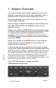
1 System Overview This manual assumes that the pilot is appropriately licensed, is proficient in operation of the aircraft and its equipment, and is in compliance with all Federal Aviation Regulations (FARs). All images contained in this manual are for reference use only, and are subject to change. Avidyne strongly recommends that pilots use the DFC90 system only under VFR conditions until completely familiar with its operation and use.
FUNCTIONAL OVERVIEW The Avidyne DFC90 autopilot supports the following functions: Flight Director Heading Capture/Hold NAV Tracking GPSS Mode Approach Mode (includes LOC, ILS, VOR, BC, LPV, LNAV/VNAV, LNAV+V) Altitude Hold Altitude Capture Vertical Speed Hold Indicated Airspeed Mode Straight and Level Speed-based Envelope Protection (EP™) Full-time Envelope Alerting (EA™) (requires Avidyne PFD 8.0.4 or later or Aspen PFD 2.
GENERAL AUTOPILOT OPERATIONS The Digital Flight Control (DFC) DFC90 autopilot has been designed to be a retrofit digital autopilot. It requires an Avidyne PFD (Release 8.0.2 or later PFD) or an Aspen EFD1000 PFD (Release 2.6 or later Pilot Pro PFD). In a DFC-equipped airplane, the autopilot uses the output of the Air Data and Attitude-Heading Reference System (ADAHRS) embedded in the PFD and is therefore an attitude-based autopilot.
PRIMARY LOCATION FOR BUG/TARGET SETTING The primary location for setting both the IAS and VS targets are via the dedicated knobs on the autopilot control head. The primary location for setting the HDG and ALT targets are via line select keys and right-hand knob on the Avidyne PFD or the right-hand knob on the Aspen PFD. VS target can optionally be set via a line select key and righthand knob on the Avidyne or Aspen PFD. IAS target can optionally be set via the left-hand knob on the Aspen PFD.
ARMED VS ENGAGED MODES INDICATIONS The DFC-series of autopilots has readily distinguishable armed vs. engaged modes in order to provide the user higher awareness of the current autopilot state and upcoming state transitions. An armed mode is defined as a state that will be captured when and if the airplane crosses that target. Armed modes are indicated by a cyan (blue) color on both the autopilot control panel and on the PFD mode annunciator strip.
MODE TRANSITION INDICATION Automatic transition from armed (cyan) to engaged (green) states is indicated by the cyan armed button on the autopilot control panel and mode annunciation on the PFD changing to green and flashing for up to 10 seconds. Note that the engaged (green) autopilot mode annunciators will also flash when in underspeed or overspeed conditions.
ENVELOPE PROTECTION (EP™) The DFC90 system provides speed-based Envelope Protection (EP™) (underspeed and overspeed warnings and protection) when in any coupled autopilot mode. NOTE No Envelope Protection in Flight Director Mode Envelope Protection (EP™) is not provided during flight director-only (non-coupled) operations.
Similarly, Envelope Protection (EP™) will provide high-speed protection and alerting near Vne. In this case, as Vne is approached in AP mode, the autopilot will adjust pitch as required to maintain an airspeed near Vne. Aircraft bank angle is not adjusted by the autopilot during overspeed protection. Depending on conditions (e.g. rapidly changing airspeed, turbulence, etc.), it is possible for Vne to be exceeded.
FULL-TIME ENVELOPE ALERTING (EA™) NOTE Envelope Alerting Requires Flap Input For the underspeed Full-Time Envelope Alerting (EA™) function to be available when the autopilot is in standby (“AP Ready”), a wiring modification must be made that allows the autopilot to recognize actual flap position. Not accomplishing this wiring modification to the aircraft harnessing means there is no Full-time Envelope Alerting (EA™) for underspeed conditions when the autopilot is in standby mode.
NOTE Suppression of Full-time Envelope Alerting Full-time Envelope Alerting (EA™) is suppressed during very low power (near idle) conditions when flaps are set to the full-flap position in order to minimize nuisance calls in the landing phase. Fulltime Envelope Alerting (EA™) is also suppressed anytime Indicated Airspeed is less than 50 KIAS.
bars present and no autopilot mode annunciators aside from the “AP READY” one along the top edge of the PFD. If an underspeed condition is recognized, an “UNDERSPEED” text alert is displayed on the PFD and a “CAUTION, UNDERSPEED” aural alert is played in the headsets and is repeated approximately every 6 seconds until the condition is no longer valid. The trigger for this Envelope Alerting (EA™) underspeed alert is when the system has determined 1.2Vs has been reached.
To disable Full-time Envelope Alerting (EA™), pull the autopilot circuit breaker. (* In cases of pre-Rel 8.0.4 Avidyne PFD code combined with post-Rel 2 DFC90 code, the active (green) autopilot mode annunciators will flash during Underspeed conditions. This is a normal consequence of maintaining backward compatibility.) BARO ADJUST Upon input of a new barometric altimeter setting, the autopilot automatically re-captures the previously set target altitude, without further action required from the pilot.
ENGAGEMENT AND HOLD LIMITS The DFC90 has maximum engagement limits beyond which the autopilot may not allow a mode to be selected, and maximum hold limits for various parameters. The engagement limits of the autopilot are wider than the hold limits. If the autopilot is engaged between the maximum engagement limits and the maximum hold limits, the autopilot will reduce the value to be within the published maximum hold limits.
COMPARATORS The DFC90 autopilot is always running comparators in the background. There are several types of comparators running during operation of the autopilot as noted in the chart below. If conflicting information is provided, the comparator identifying the conflict with the accompanying pilot indication and autopilot behavior is noted in the table below: Type of Comparator Indication to Pilot Autopilot behavior Internal kinematic comparator within the AHRS (compares AHRS state data with itself, eg.
AUTOPILOT ENGAGEMENT From a standby state (autopilot has power, “AP READY” displayed but no modes are engaged and the airplane is within the engagement limits defined above), pressing any button on the autopilot will engage the DFC autopilot. If a specific lateral and/or vertical mode is not pressed, the system will default to ROLL hold mode in the lateral channel and PITCH hold mode in the vertical channel.
Press the “AP” button on the autopilot control panel (servos will disconnect but the flight director will remain active); Pull the circuit breaker(s) controlling the power to the autopilot. For those aircraft with the stall warning wired directly to the autopilot, the autopilot will also disconnect if the stall warning alarm is present in the aircraft. In most cases, the autopilot disconnect will be accompanied by a 16-beep disconnect aural alert.
The flight director command bars in a DFC90 autopilot are designed for easy use and improved performance during uncoupled autopilot operations. During coupled operations (both “AP” and “FD” buttons lit), pressing the “FD” button will have no effect. Pressing the “AP” button in this state will toggle the “AP” mode on/off. It is a good way to disconnect the servos but continue to have flight director command bars present.
PFD ANNUNCIATIONS The top strip of the PFD is dedicated for autopilot mode annunciators. Active modes are depicted in green and armed modes are depicted in cyan. Alerts are depicted in yellow and are listed in order of priority. If multiple alerts are received, then the highest priority message is displayed. Whenever “UNDERSPEED” or “OVERSPEED” are displayed while the autopilot is coupled, all engaged (green) autopilot mode annunciators will flash.
2 Normal Startup Sequence ................................................2-2 POWER CONSIDERATIONS .......................................................2-2 SELF-TEST/ALIGNMENT ............................................................2-2 BRIGHTNESS CONTROLS .........................................................2-2 PRE-FLIGHT TEST ......................................................................2-3 BEFORE TAKEOFF TECHNIQUES .............................................
2 Normal Startup Sequence POWER CONSIDERATIONS The DFC90 consumes 0.25A when no servos are in operation and up to 0.9A with all servos operating at 100% duty cycle. There is no on/off switch to the DFC-series of autopilots. As soon as the governing power bus is active through normal aircraft checklist steps, the autopilot will power up. SELF-TEST/ALIGNMENT The DFC autopilot requires two events to be fully functional.
PRE-FLIGHT TEST 1. Ensure “AP READY” is displayed on PFD annunciator strip 2. Press AP button on autopilot control head a. Ensure AP button is lit in green b. Ensure “AP”, “ROLL”, “PITCH” annunciations are depicted in green on the PFD annunciator strip 3. Set the Heading Bug to be approximately 90 degrees off current aircraft heading 4. Press HDG button on autopilot control head a. Ensure HDG button is lit in green b.
NOTE Preflight Test Does Not Test Every Aspect of AP The Pre-Flight test of the DFC90 autopilot outlined above will check the functionality of such items as the ability of the autopilot to engage and disconnect, the ability of the autopilot to engage the roll axis control surfaces, and the communications between the autopilot and the PFD. However, the Pre-Flight test does not check the function of every item essential to the use of the autopilot.
3 Climb-out/Enroute .............................................................3-2 NORMAL OPERATING MODES ..................................................3-2 Pitch Mode ............................................................................................ 3-2 Roll Mode ............................................................................................. 3-2 Heading (HDG) Mode ........................................................................... 3-3 Navigation (NAV) Mode ............
3 Climb-out/Enroute This section covers normal modes of the autopilot during climbout and enroute operations as well as procedures, mode control and display. NORMAL OPERATING MODES Envelope Protection (EP™) is active in all of the autopilot modes defined below. PITCH MODE In Pitch Hold mode, the autopilot will maintain a constant pitch from the moment of mode entry. If the mode was entered at a pitch that exceeds the maximum hold limit, the pitch will be reduced to the maximum hold limit value.
HEADING (HDG) MODE Heading mode is entered by pressing the “HDG” button on the autopilot control panel. The system will light up the control panel button in green and track the set heading bug value and the bug will become solid magenta. Select a new heading by moving the heading bug at any time while the autopilot is in heading mode and the autopilot will track the new bug value. The aircraft will turn in the same direction that the heading bug knob was turned.
to a wind-corrected heading until the station signal is re-acquired and signal tracking can resume. For the condition when Nav mode is conducting its own 45 degree intercept, this is depicted by a cyan “NAV” autopilot mode annunciator indicating Nav mode is armed, followed by a green “45 INT” indicating the system is currently conducting a 45 degree intercept of the commanded Nav course.
ALTITUDE HOLD (ALT) MODE Altitude Hold mode is entered by pressing the “ALT” button on the autopilot control panel. The system will light up the control panel button in green, sync the altitude bug on the altimeter to the nearest 10 feet to current altitude (Avidyne PFD) or current altitude (Aspen PFD) and turn it solid, and hold the altitude at the time of mode entry.
A secondary method is via the left knob on the Aspen PFD page. The autopilot modes annunciator indication is green “IAS”. There is no armed (cyan) IAS mode. VERTICAL SPEED (VS) HOLD MODE Vertical Speed Hold mode is entered by pressing the “VS” button on the autopilot control panel. The system will light up the control panel button in green, turn the VS bug solid and adjust the aircraft climb/descent rate as required to match the bug setting. The range of settable VS targets is ±1600 fpm.
NOTE Logical Combination of Commanded Targets A logical combination of commanded autopilot targets means a combination of the altitude bug and either the vertical speed bug or indicated airspeed bug that can be achieved. For example, an altitude bug that is above current aircraft altitude and a positive vertical speed bug is a logical combination. In contrast, an altitude bug that is above current aircraft altitude and a negative vertical speed bug is NOT a logical combination.
paired button. For example, for an IAS-based altitude capture, the IAS button can be pressed and held, and while that button is depressed, press the ALT button. When both are released, the speed mode will be active and the altitude mode armed just as intended. On Avidyne PFD-equipped aircraft, the altitude bug control cycles through a ‘thousands’ mode, ‘hundreds’ mode, and ‘tens’ mode with each press of the adjacent line select key.
STRAIGHT AND LEVEL NOTE Straight and Level Definition Pressing the “STRAIGHT AND LEVEL” button on the autopilot will result in a zero bank, +2 pitch angle attitude. It is not an altitude hold mode or a zero vertical speed mode, nor does it hold a heading. NOTE Straight and Level Usable Envelope The Straight and Level button and functionality were demonstrated to the POH limits of the aircraft ( 60 bank, 30 pitch), This mode is not to be relied upon to stabilize an aircraft under all conditions.
Straight and Level mode can be entered from any autopilot state, including from the off position. NOTE Limitation of Overspeed Protection in Straight and Level Overspeed protection is not ensured during initiation of Straight and Level mode. Depending on the dynamics of the airplane and the available torque in the servos, the recovery to straight and level conditions may exceed Vne.
The heading knob can be adjusted at any time (before or after entering pilot selectable intercept mode) and the system will adjust the intercept angle accordingly. The desired means of mode entry is via a simultaneous push of both the heading (HDG) and lateral nav (GPSS or NAV) buttons on the autopilot control panel. However, an alternative technique is to press and hold one of the buttons, and while that button is still depressed, press the other paired button.
CONTROL WHEEL STEERING MODE Control Wheel Steering (CWS) mode is entered by pressing the CWS button on the aircraft yoke in those aircraft that support this functionality. CWS mode allows the servos to be temporarily disengaged for the duration that the CWS button is held down, providing an opportunity for the pilot to manually maneuver the aircraft as desired without disconnecting the autopilot.
4 Approach Procedures ......................................................4-2 GENERAL BEHAVIOR .................................................................4-2 APPROACH MODES ...................................................................4-2 WAAS Approaches ............................................................................... 4-2 GPS approach (RNAV or Overlay or LNAV) .......................................... 4-5 VOR approach ............................................................
4 Approach Procedures GENERAL BEHAVIOR The integrated DFC90 and PFD system is designed to take full advantage of the auto transition capability of the GNS-430 units for flying a GPS flight plan ending in an ILS approach. Note: For those aircraft that are not equipped with a 430-family GPS Nav-Com, the Aspen PFD converts the signals such that the DFC90 should behave in accordance with these descriptions. If the GPS or NAV does not support an input, the Aspen PFD sends the input as invalid to the DFC90.
WAAS approaches are intended to flown in NAV APPR mode in the DFC90 system and thus the “Primary Nav” LSK must be set to GPS1/2. Roll commands are issued by the GPS Nav-Com in GPSS mode instead of the DFC90 and proper vertical guidance cannot be assured, hence the need to fly WAAS approaches in NAV APPR modes. Glide slope will not arm if the autopilot mode is GPSS.
must be pressed. If it is not manually changed to NAV, then an automatic switch will occur when/if a GPS glide slope signal is received. In either the manual or automatic case, the AP switches to NAV APPR. Then fly coupled to MDA. If a level off at the MDA is desired, the ALT button must be pressed on the autopilot.
NON-WAAS GPS APPROACH (RNAV OR OVERLAY OR LNAV) □ Ensure the Primary Nav LSK is set to a GPS source and a GPS approach is loaded in the GPS Nav-Com □ Press the “NAV” or “APPR” or “GPSS” buttons on the autopilot control panel □ Note that the “NAV” and “APPR” buttons on the autopilot control panel are lit in green or the “GPSS” and “APPR” buttons are lit in green if the autopilot is flying the bank commands □ Note that “NAV APPR” or “GPSS APPR” is displayed in the PFD mode annunciator section □ Execu
LOCALIZER APPROACH To fly the complete published approach, select the approach and IAF desired, load and then activate the approach at the appropriate time in the GPS Nav-Com navigator, ensure the correct navigator is selected in the PFD Primary Nav LSK, and ensure the DFC90 is in NAV mode. When flying a Vectors-To-Final approach, use the Heading knob and the “HDG” button on the autopilot control panel when ATC is issuing vectors.
ILS APPROACH INCLUDING GLIDE SLOPE INTERCEPT When flying a Vectors-To-Final approach, use the Heading knob and the “HDG” button on the autopilot control panel when ATC is issuing vectors. NAV APPR can be armed prior to capturing the localizer beam but it is highly recommended to wait until ATC clears you for the approach before arming NAV and APPR. To arm NAV APPR while still in Heading/Vectors mode, press the “HDG” and “NAV” (or “HDG” and “APPR”) buttons at the same time.
Glide slope will automatically arm if the following 4 conditions are met: 1. PFD Primary Nav LSK is set to VLOC1 or VLOC2; 2. The selected GPS Nav-Com (VLOC1 or VLOC2) has a valid localizer/glide slope frequency loaded in the active; 3. NAV mode on the DFC90 must be armed (cyan) or engaged (green). (APPR mode will also be automatically armed or engaged under these conditions); 4. The course value on the PFD is set to any value that would create a “front course” condition.
PROCEDURE TURN ILS OR LOCALIZERS The procedure for an ILS or Localizer with a procedure turn in a combined DFC90/430 system is the same as the straight-in procedures except that Heading mode should be used on the procedure turn. This is accomplished by pressing the “HDG” button on the autopilot control panel and then using the heading knob on the PFD. Command the heading bug to the outbound procedure turn heading. Hold that heading until the point at which it is time to turn inbound.
BACK COURSE APPROACHES Always ensure the front course is set in the Selected Course window. The system will recognize it is on a back course when the VHF receiver is locked onto a valid signal and there is a sufficient difference between aircraft heading and the selected course. There is no “REV” or similar button in a DFC90 autopilot.
5 Abnormal Procedures ......................................................5-2 GENERAL FAILURE MODE INFORMATION ...............................5-2 Loss of PFD Display (AHRS still Operational) ....................................... 5-3 Loss of PFD Bezel buttons and KNobs ................................................. 5-4 Loss of PFD Display and Bezel buttons ................................................ 5-5 Loss of Turn Coordinator ....................................................................
5 Abnormal Procedures GENERAL FAILURE MODE INFORMATION The only failure modes that result in the loss of a DFC-series autopilot are when the system AHRS is unavailable (Red-Xs over the attitude display) or when the PFD has no power. Each autopilot contains an internal data recorder for use during service operations. The contents of the data logs remain the property of Avidyne.
LOSS OF PFD DISPLAY (AHRS STILL OPERATIONAL) Failure Indication: A loss of PFD display condition is identified by a display being unreadable but PFD bezel button lights are still lit. Functionality Lost: Under these conditions, if there are no readable PFD displays left, there is a degradation in the ability to enter some autopilot commands/bug settings. Note that in this case, the internal components of the PFD are all fully functional, including the AHRS.
LOSS OF PFD BEZEL BUTTONS AND KNOBS Failure Indication: A failure of the PFD bezel buttons/knobs is indicated by the display still being present and functional but the bezel buttons/knobs are inoperative. Functionality Lost: The ability to enter altitude and heading autopilot commands and target bugs will be lost. The ability to change which GPS Nav-Com navigator is driving the PFD nav solution will also be lost. Recommended Pilot Action: Use the autopilot in the remaining usable modes (e.g.
LOSS OF PFD DISPLAY AND BEZEL BUTTONS Failure Indication: A failure of the PFD display and bezel buttons is indicated by the display being blank or a solid color such as green, and the bezel buttons are inoperative. Functionality Lost: The ability to enter some autopilot commands/target bugs will be degraded or lost. The rest of the PFD remains functional in this case (e.g. internal ADAHRS, automatic communication with MFD rd and 3 party avionics, etc).
LOSS OF TURN COORDINATOR In Cirrus SR2X or Piper PA46 installations where the DFC90 is replacing a STec 55X autopilot, the DFC90 will use the previously installed turn coordinator as a source of attitude comparison. In all other cases, there is no connectivity to a turn coordinator and this scenario does not apply. Failure Indication: A failure of the aircraft turn coordinator is indicated by an alert message (“TC FAIL”) displayed in the autopilot mode annunciator area of the PFD displays.
LOSS OF AHRS (SINGLE PFD EQUIPPED AIRCRAFT) Failure Indication: A failure of an AHRS is identified by Red-Xs over the attitude and HSI compass card and an autopilot disconnect (if previously engaged). Additionally, a yellow “AUTOPILOT INOP AHRS FAIL” message is displayed in the center of the autopilot mode annunciator area on the PFD. Functionality Lost: A loss of AHRS will result in a loss of all autopilot functionality.
LOSS OF AIR DATA This scenario is only applicable to Avidyne PFD-equipped aircraft. Failure Indication: A failure of the on-board air data system(s) is indicated by the airspeed, altimeter and vertical speed tapes being replaced by Red-Xs.
TOTAL LOSS OF PFD (SINGLE PFD EQUIPPED AIRCRAFT) Failure Indication: A total failure of the PFD is indicated by both the display and bezel buttons all blank/unlit. Functionality Lost: A loss of the PFD will result in a complete loss of autopilot functionality. Recommended Pilot Action: Immediately transition to hand-flying via the standby instruments and seek VMC as soon as feasible. Consider attempting a single PFD warmstart by cycling both PFD circuit breakers for less than 20 seconds.
LOSS OF ENGINE Loss of engine does not affect the DFC90 operation but the DFC90 autopilot can be useful during loss of engine situations. One technique is to set the IAS bug to best glide speed and engage IAS mode in the event of engine-out conditions. The autopilot will adjust aircraft pitch as required to slow down, or speed up to achieve Vg, freeing up time to perform other cockpit duties during this emergency situation.
OTHER ERROR MODES Autopilot failures that prevent any operation are annunciated across the center of the PFD mode annunciator strip in amber (yellow) as shown in the examples immediately below. PFD Autopilot Annunciator (Avidyne top image, Aspen bottom image) GENERAL OR UNKNOWN FAILURES Failure Indication: If the DFC-PFD system recognizes that the autopilot is invalid but can not decipher the reason, a yellow “AUTOPILOT INOP” message is displayed along middle of the PFD annunciator strip.
If the autopilot does not conduct a successful automatic restart, consider attempting an autopilot restart by cycling the autopilot circuit breaker. AHRS-TC MISCOMPARE DURING GROUND OPERATIONS In Cirrus SR2X or Piper PA46 installations where the DFC90 is replacing a STec 55X autopilot, the DFC90 will use the previously installed turn coordinator as a source of attitude comparison. In all other cases, there is no connectivity to a turn coordinator and this scenario does not apply.
BUILT-IN TEST (BIT) FAILURE Failure Indication: If the DFC-PFD system recognizes that the autopilot is invalid due to failing an internal self-test, a yellow “AUTOPILOT INOP SELF TEST FAIL” message is displayed along middle of the PFD annunciator strip. Functionality Lost: All autopilot functionality will be lost for the duration of this message display. It is most likely experienced during initial power on of the autopilot during ground operations and therefore, would not allow autopilot engagement.
AHRS ALIGNING Failure Indication: If the PFD AHRS has not finishing aligning, a yellow “AUTOPILOT INOP AHRS ALIGNING” message is displayed along the middle of the PFD annunciator strip. This message should be expected to be seen during all normal ground operations in the course of all standard alignments. Functionality Lost: Since the DFC autopilot requires a fully aligned AHRS for its attitude source, the autopilot will remain non-functional until the AHRS is aligned and the message is removed.
NO COMMUNICATION WITH AUTOPILOT Failure Indication: If the PFD stops receiving data from the autopilot, a yellow “NO COMMUNICATION WITH AUTOPILOT” message is displayed in the center of the PFD annunciator strip. Functionality Lost: All autopilot functionality will be lost for the duration of this message display.
TRIMMING UP/DOWN Failure Indication: If the DFC-PFD system recognizes that trim has been running for an excessive duration, a yellow “TRIMMING UP” or “TRIMMING DN” message is displayed on the PFD. Functionality Lost: No functionality has been lost. In all cases, the trim system can be manually overridden with pilot-controlled control stick/yoke inputs.
GPSS INVALID Failure Indication: If the DFC-PFD system recognizes that the autopilot mode is GPSS but the roll steering information from the GPS Nav-Com is invalid, a yellow “GPSS INVALID” message is displayed on the PFD.
NAV INVALID Failure Indication: If the DFC-PFD system recognizes that the VHF lateral nav signal from the GPS Nav-Com is invalid, a yellow “NAV INVALID” message is displayed on the PFD. In addition, the Horizontal Deviation Indicator (HDI)/Lateral Deviation Indicator (LDI) along the bottom edge of the ADI will be Red-X’d. The autopilot will command a wind corrected course hold and, if sufficient power is available, the flight path angle at the time the system displayed “NAV INVALID”.
GLIDE SLOPE INVALID Failure Indication: If the DFC-PFD system recognizes that the VHF vertical nav signal (glide slope) from the GPS Nav-Com is invalid, a yellow “GS INVALID” message is displayed on the PFD. In addition, the Vertical Deviation Indicator (VDI) along the right edge of the ADI will be Red-X’d. Functionality Lost: The ability to track a VHF vertical course (Glide Slope) from the selected GPS Nav-Com navigator has been lost.
TC FAIL In Cirrus SR2X or Piper PA46 installations where the DFC90 is replacing a STec 55X autopilot, the DFC90 will use the previously installed turn coordinator as a source of attitude comparison. In all other cases, there is no connectivity to a turn coordinator and this scenario does not apply. Failure Indication: If the DFC-PFD system recognizes that the blind-mounted turn coordinator has failed, a yellow “TC FAIL” message is displayed on the PFD.
AHRS MISCOMP In Cirrus SR2X or Piper PA46 installations where the DFC90 is replacing a STec 55X autopilot, the DFC90 will use the previously installed turn coordinator as a source of attitude comparison. In all other cases, there is no connectivity to a turn coordinator and this scenario does not apply.
NO PFD COMM Failure Indication: If the autopilot stops receiving data from the PFD, a yellow “NO PFD COMM” message is displayed on the PFD. Functionality Lost: All autopilot functionality will be lost. Recommended Pilot Action: Immediately transition to hand-flying the aircraft. Consider attempting a single PFD warmstart by cycling both PFD circuit breakers for less than 20 seconds (if Avidyne PFD equipped).
MSR FAIL Failure Indication: If the autopilot computer determines that it can no longer read from, or write to the internal maintenance and safety recorder, a yellow “MSR FAIL” message is displayed on the PFD. In addition, all aurals associated with the autopilot (e.g. full-time envelope alerting, envelope protection alerts), will be absent.
AUDIO FAIL Failure Indication: If the autopilot computer determines that it has corrupted or missing audio files, a yellow “AUDIO FAIL” message is displayed on the PFD. In addition, all aurals associated with the autopilot (e.g. full-time envelope alerting, envelope protection alerts), will be absent. Functionality Lost: The autopilot will still be fully functional in all pilot-usable modes but all autopilot aural alerts will be unavailable.
SERVO LIMIT Pilot Indication: If the autopilot computer determines that the roll-axis servo limit has been reached, a yellow “SERVO LIMIT” message is displayed on the PFD. Since the autopilot may stop following lateral commands, this could appear to the pilot as an uncommanded roll or a failure to follow the commanded lateral target. Functionality Lost: The autopilot will still be fully functional but the roll axis may not follow the autopilot commands since the servo has reached its maximum limit.
BANK LIMIT Pilot Indication: If the autopilot computer determines that the aircraft has exceeded the POH bank limit, a yellow “BANK LIMIT” message is displayed on the PFD. In addition, a “Caution, Excessive Bank” aural alert is played in the headsets. Functionality Lost: None. Recommended Pilot Action: Reduce the manual bank angle command.
6 Limitations and Performance ..........................................6-2 LIMITATIONS ...............................................................................6-2 SOFTWARE COMPATIBILITY AND NOTES ...............................6-2 GENERAL PERFORMANCE – CIRRUS AIRCRAFT ...................6-5 PERFORMANCE IN PITCH TRIM-ONLY AIRCRAFT ..................6-6 PERFORMANCE IN NON-CIRRUS AIRCRAFT...........................
6 Limitations and Performance LIMITATIONS See the individual aircraft Pilot Operating Handbook (POH) Supplement for altitude, airspeed and other limitations with respect to DFC90 autopilot operations. SOFTWARE COMPATIBILITY AND NOTES The following table identifies authorized combinations of PFD and autopilot code and any associated operational notes. For the purposes of this table, differences noted in the Operational Notes column are when compared to DFC90 Pilot Guide 600-00252-000 Rev 05.
PFD Version AP Version* Wired for Flap Position? Avidyne 8.0.6 or 8.0.5 or 8.0.4 2 No Operational Notes No Flap Overspeed alert Underspeed alerts in both Envelope Protection and Envelope Alerting use a more conservative no-flap speed value No Envelope Alerting Underspeed functionality when AP is in standby (AP Ready) state Underspeed alerts are not suppressed in the flare and on rollout Avidyne 8.0.6 or 8.0.5 or 8.0.
PFD Version AP Version* Wired for Flap Position? Operational Notes No Audio Fail alert No Servo Limit alert MSR Fail means no AP Disconnect tones Avidyne 8.0.3 1 or 2 Yes or No Same as above except that if the DFC90 is Version 2, then the DFC90 will not disconnect during AHRS-TC Miscompares and the TRIMMING UP/DOWN message may be more prevalent Avidyne 8.0.
GENERAL PERFORMANCE – CIRRUS AIRCRAFT The input forces required for roll-axis control surface actuation are demonstrably light and it is not difficult to force the servo (roll trim spring cartridge) to drive to its limit. By design, reaching the physical limit causes a micro-switch to be tripped which effectively decouples the autopilot commands from the flight control surfaces.
PERFORMANCE IN PITCH TRIM-ONLY AIRCRAFT As noted earlier, all modes and behaviors described in this manual work both in aircraft with pitch servos and those without (pitch trim-only) with the exception of the reaction to manual electric trim inputs.
Index Annunciations Aural Alerts, 1-5 Mode Annunciator Strip, 1-6 PFD Annunciators, 1-19 Approaches WAAS, 4-2 GPS, 4-5 VOR, 4-5 Localizer, 4-6 ILS, 4-7 Procedure Turns, 4-9 Back course, 4-10 Missed Approach, 4-10 Autopilot Controls, 1-4 Autopilot Modes Pitch mode, 3-2 Roll mode, 3-2 Heading mode, 3-3 Nav mode, 3-3 GPSS mode, 3-4 Altittude Hold mode, 3-5 IAS Hold mode, 3-5 VS Hold mode, 3-6 Altitude Capture mode, 3-6 Straight and Level mode, 3-9 Pilot-select intercept angle, 3-10 Glide slope, 4-8 Control Whe
Website There is a dedicated website that provides more information on this product at http://www.dfc90.com FAQs http://www.avidyne.com/downloads/products/dfc90/DFC90DFC100-FAQs.pdf Service Hotline A hotline has been established to service questions or issues regarding Avidyne products. The U.S. Toll Free number is 1-888-723-7592. International toll free numbers are listed at http://www.avidyne.com/contact/intphones.
AVIDYNE CORPORATION 55 Old Bedford Road Lincoln MA 01773 P 781 402 7400 | F 781 402 7599 Toll Free 800-AVIDYNE (800 284 3963) www.avidyne.com http://www.avidyne.com/products/dfc90/index.