
Specifications


Table Of Contents
- Contents
- Introduction
- Installation and Authorization
- Session and Track Features
- Advanced Editing Features
- Advanced Automation Features
- AutoJoin with Latch Mode
- Touch/Latch Mode
- Trim Mode
- Composite Automation Playlist
- Copy Track Automation to Sends
- AutoMatch
- Prime Controls for Writing Automation in Latch Mode
- Glide Automation
- Trim Automation
- Write Automation to the Start, End, or All of a Track or Selection
- Write Automation to the Next Breakpoint or to the Punch Point
- Overwrite or Extend Mute Automation
- Snapshot Automation
- Preview Automation
- Capture Automation
- VCA Master Track Automation
- Surround Features
- Pro Tools Audio Connections for 5.1 Mixing
- Configuring Pro Tools for Multichannel Sessions
- Default I/O Selectors in I/O Setup
- 5.1 Track Layouts, Routing, and Metering
- Routing Audio for Surround Mixing
- Multichannel Audio Tracks
- Multichannel Signal Routing
- Paths in Surround Mixes
- Example Paths and Signal Routing for a Surround Mix
- Introduction to Pro Tools Surround Panning
- Output Windows
- Surround Panner Controls
- Panning Modes
- Divergence and Center Percentage
- LFE Faders in Multichannel Panners
- Pan Playlists
- Surround Scope Plug-In
- Video Features
- Included Plug-Ins
- Index
Chapter 6: Surround Features 83
Example Paths and Signal
Routing for a Surround Mix
The examples that follow show how Auxiliary
Inputs, Master Faders, and other Pro Tools sig-
nal routing features can be used for stem mixes,
submixes, and similar project needs.
In these examples, music and effects are being
mixed for a trailer, in 5.1 surround. Separate
stem mixes (for music and for effects) are to be
mastered to 8-track MDM.
Example Multichannel Paths
Signal routing is the key element in any
Pro Tools surround session. Signal routing is
configured and defined in the I/O Setup dialog.
Example Output Paths
Figure 4 shows output paths defined in the I/O
Setup dialog of an example session that was cre-
ated using a 003.
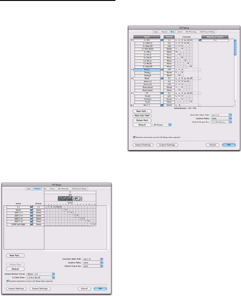
Example Bus Paths
Figure 5 shows example bus paths.
Output bus main paths and sub-paths have been
defined for the 5.1 Mix.
An LCR format internal mix bus path (“Dialog”)
and two 5.1 format paths (“Music” and “FX”)
have been defined, each with several sub-paths.
Figure 4. I/O Setup, example output paths
Figure 5. I/O Setup, example bus paths