XMON EUCON™ Software Application User Guide
Legal Notices This guide is copyrighted ©2011 by Avid Technology, Inc., with all rights reserved. Under copyright laws, this guide may not be duplicated in whole or in part without the written consent of Avid.
Contents Chapter 1. Introduction to the XMON EUCON Software Application . . . . . . . . . . . . . . . . . . . . . . . . . . . . . . . . . . . . 5 System Requirements and Compatibility . . . . . . . . . . . . . . . . . . . . . . . . . . . . . . . . . . . . . . . . . . . . . . . . . . . . . . . . . . . . . 5 What’s Included . . . . . . . . . . . . . . . . . . . . . . . . . . . . . . . . . . . . . . . . . . . . . . . . . . . . . . . . . . . . . . . . . . . . . . . . . . . . . . 5 About This Guide. . . . . . .
iv XMON EUCON Software Application User Guide
Chapter 1: Introduction to the XMON EUCON Software Application The XMON EUCON™ Software Application is a simple EUCON-enabled utility that lets you control the XMON hardware from an Avid MC Pro or System 5-MC control surface. Once configured, the Control Room and Monitor section can be locked to XMON, letting you continue to control XMON monitoring from the control surface while switching to other software applications and workstations.
The names of Commands, Options, and Settings that appear on-screen are in a different font. The names of keys on System 5-MC and MC Pro hardware are in bold (such as SEL). The following symbols are used to highlight important information: User Tips are helpful hints for getting the most from your system. Important Notices include information that could affect your data or the performance of your system. Shortcuts show you useful keyboard or mouse shortcuts.
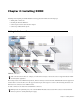
Chapter 2: Installing XMON Installing and configuring the XMON EUCON Software application includes the following steps: • Making audio connections • Installing the M-Audio MIDI Uno • Connecting the Control Cable Breakout Adaptor • Connecting a Talkback microphone Making Audio Connections XMON audio connections Audio connections shown above are examples for Avid ICON work surfaces. Not all connections are supported with the XMON EUCON Software Application.
XMON-to-Pro Tools|HD Wiring Diagram The following diagram shows basic XMON connections for a Pro Tools|HD system with an HD I/O that has 16 analog outputs.
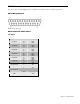
DB-25 Connectors This section shows a wiring diagram for each of XMON’s seven DB-25 connectors, and their pinout tables.
Surround1 Inputs Signal Name Surround Input1-1 Surround Input1-2 Surround Input1-3 Surround Input1-4 Surround Input1-5 Surround Input1-6 Surround Input1-7 Surround Input1-8 GND Pin# 24 12 25 10 23 11 21 9 22 7 20 8 18 6 19 4 17 5 15 3 16 1 14 2 13 26 27 Signal Type Input+ InputGND Input+ InputGND Input+ InputGND Input+ InputGND Input+ InputGND Input+ InputGND Input+ InputGND Input+ InputGND GND Surround2 Inputs Signal Name Surround Input2-1 Surround Input2-2 Surround Input2-3 Surround Input2
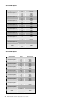
2Track Inputs Signal Name 2Track Input1 2Track Input2 2Track Input3 2Track Input4 2Track Input5 2Track Input6 2Track Input7 2Track Input8 GND Pin# 24 12 25 10 23 11 21 9 22 7 20 8 18 6 19 4 17 5 15 3 16 1 14 2 13 26 27 Signal Type Input+ InputGND Input+ InputGND Input+ InputGND Input+ InputGND Input+ InputGND Input+ InputGND Input+ InputGND Input+ InputGND GND Cue Outputs Signal Name SLS Output L SLS Output R Cue Output1L Cue Output1R Cue Output2L Cue Output2R Cue Output3L Cue Output3R
Main SPK Outputs Signal Name Main 1 (L) Main 2 (Lc) Main 3 (C) Main 4 (Rc) Main 5 (R) Main 6 (SurL) Main 7 (SurR) Main 8 (LF) GND Pin# 24 12 25 10 23 11 21 9 22 7 20 8 18 6 19 4 17 5 15 3 16 1 14 2 13 26 27 Signal Type Output+ OutputGND Output+ OutputGND Output+ OutputGND Output+ OutputGND Output+ OutputGND Output+ OutputGND Output+ OutputGND Output+ OutputGND GND Alt SPK Outputs Signal Name Alt 1 (L) Alt 2 (Lc) Alt 3 (C) Alt 4 (Rc) Alt 5 (R) Alt 6 (SurL) Alt 7 (SurR) Alt 8 (LF) GND Pi
TB/LB Signal Name TB Input2 LB Input1 LB Input2 AFL Input1 AFL Input2 Mini Spk L Mini Spk R TB OUT GND Pin# 24 12 25 10 23 11 21 9 22 7 20 8 18 6 19 4 17 5 15 3 16 1 14 2 13 26 27 Signal Type Input+ InputGND Input+ InputGND Input+ InputGND Input+ InputGND Input+ InputGND Output+ OutputGND Output+ OutputGND Output+ OutputGND GND Chapter 2: Installing XMON 13
Installing the M-Audio MIDI Uno Windows 7 and Mac OS X If you are using Windows 7 or Mac OS X, simply plug in your Uno to the computer’s USB port, the proceed to “Connecting the Control Cable Breakout Adapter” on page 15. Since the M-Audio MIDI Uno is class-compliant, it does not require additional drivers. Installation for Advanced Windows 7 Users Windows 7 users who fall into the following categories should install the special M-Audio drivers for optimal performance.
Connecting the Control Cable Breakout Adapter The Control Cable Breakout Adapter lets the XMON EUCON Software Application communicate with and control the XMON hardware. To connect the Control Cable Breakout Adapter and M-Audio MIDI Uno: 1 Connect the 15-pin end of the Control Cable Breakout Adapter to the Control port on the back panel of the XMON hardware. 2 Connect the M-Audio Uno’s MIDI OUT cable (four feet, attached) to the MIDI IN port on the Control Cable Breakout Adapter.
Installing and Configuring the XMON EUCON Software Application The XMON EUCON Software Application installer includes Mac and Windows audio drivers that integrate with the applications you use with XMON. To install the XMON EUCON Software Application: 1 On the XMON EUCON Software Application disc, double-click the XMON Install.pkg file (Mac) or SetupXMON.exe (Windows). 2 Follow the on-screen instructions.
Locking the Surface to XMON The Control Room and Monitor section of the MC Pro control surface must be locked to the XMON software application to retain control of the studio levels while other applications or another workstation is in focus. To lock the Control Room section to the XMON EUCON Software Application: 1 Make sure the MC Pro is attached to the workstation running the XMON EUCON Software Application. 2 Make sure the XMON EUCON Software Application is in focus (i.e., the front-most application).
XMON EUCON Software Application User Guide
Chapter 3: Using XMON XMON to EUCON Mapping This section clarifies the terminology used for the XMON and MC Pro/System 5-MC hardware. Control Room The Control Room section of the MC Pro/System 5-MC can route input sources to three sets of outputs. Main Spkrs Routes selected source(s) to the Main 1–8 (7.1-channel) outputs on the XMON hardware. Alt 1 Spkrs Routes selected source(s) to the Alt 1–8 (7.1-channel) outputs on the XMON hardware.
Selecting Sources from MC Pro The MC Pro surface lets you assign XMON input sources to the Control Room and Monitor outputs. Control Room To select input sources for the Control Room: Press the SETUP key in the Control Room section of the MC Pro surface. The Touchscreen that appears displays the available sources across the top row in blue. MC Pro Control Room Setup Touchscreen 1 Press a gray button directly below a source to toggle the corresponding source on.
Control Room Sources The following input sources are available for the Control Room: • Main • Surround • Stereo 1 • Stereo 2 • Stereo 3 • Stereo 4 • Listenback • AFL Monitors A–D To select input sources for the four Monitor feeds: 1 Press the SETUP key in the Control Room section of the MC Pro surface. The Setup: Monitor Touchscreen displays the available sources in the Monitor Source column. 2 Touch a source in the list to activate it for the Monitor feed.
Setting Control Room, Monitor, and Dim Levels Control Room Levels The MC Pro main Control Room knob adjusts the playback level for the three Control Room output feeds independently. To adjust the level of the Main Spkrs (7.1), Alt 1 Spkrs (7.1), or Alt 2 Spkrs (Stereo): 1 Select Main Spkrs, Alt 1 Spkrs, or Alt 2 Spkrs below the MC Pro Control Room knob. 2 Adjust the Control Room knob to the desired playback level for the selected speaker feed.
Speaker Management Speaker Mapping The Speakers buttons at the bottom of the Control Room Setup screen correspond to the eight outputs for the currently selected Control Room feed: Main, Alt, Mini. When Alt 2 Spkrs is selected on the MC Pro, the Control Room Setup screen speaker selector array shows only the two speakers for the Mini output feed. Speakers On and Off The Speakers outputs are toggled on and off by clicking the eight buttons on the Control Room Setup screen.
XMON EUCON Software Application User Guide
Avid Technical Support (USA) Product Information 2001 Junipero Serra Boulevard Daly City, CA 94014-3886 USA Visit the Online Support Center at www.avid.com/support For company and product information, visit us on the web at www.avid.