
User guide


Table Of Contents
- Contents
- Introduction to System 5
- Master Facilities and Channel Strip
- Control, Layouts and Snapshots, and Linking
- Chapter 8: Machine Control (S5P Only)
- Chapter 9: Control Groups and Multi Format Masters
- Chapter 10: Layouts and Snapshots
- Chapter 11: Linking (S5P Only)
- Chapter 12: Dynamic Automation (S5P Only)
- Chapter 13: GPI/O Event System
- Chapter 14: CM403 Film/Post Module (S5 Only)
- Chapter 15: Hybrid Pilot and System 5 Fusion Options
- Appendix A: Compliance Information
System 5 Digital Audio Mixing System User Guide78
Inputs
Each channel has an A and B input. See “Channel Patch Points” on page 75 to learn how to assign sources for these inputs. The Inpt
knob (bottom) can feed A, B, or A+B to the channel. These two inputs can be used in many clever ways, but a common application
is one mic and one line. Another common use is for monitor inputs: Channel 1A is from the Group 1 Bus output, while 1B is from
the recorder’s track 1 output. The A/B source switch then acts as a bus/tape switch.
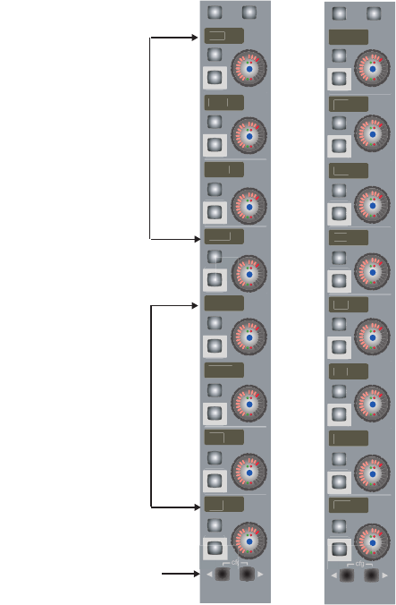
1 Press the Input function key to display the input controls on the knobset (see figure below).
2 Press the key to display the B input page with the same controls as the A input.
3 Press the key again to display the Signal Processing In/Out page.
Atrm and Aphs have corresponding controls for the B input; Dly and Inp adjust one parameter that applies to both inputs.
Input A (left) and Signal Processing In/Out (right) knobsets
g
HiZ
4
8
V
HPF
G
ai
n
A
t
r
m
A
p
hs
D
l
y
In
p
Analog Controls
Page keys display
Input B and Signal Processing
In/Out pages
Digital Controls
D
l
y
Dyn
F
ad
M
tr
E
Q
Fil
t
In
s