
User guide


Table Of Contents
- Contents
- Introduction to System 5
- Master Facilities and Channel Strip
- Control, Layouts and Snapshots, and Linking
- Chapter 8: Machine Control (S5P Only)
- Chapter 9: Control Groups and Multi Format Masters
- Chapter 10: Layouts and Snapshots
- Chapter 11: Linking (S5P Only)
- Chapter 12: Dynamic Automation (S5P Only)
- Chapter 13: GPI/O Event System
- Chapter 14: CM403 Film/Post Module (S5 Only)
- Chapter 15: Hybrid Pilot and System 5 Fusion Options
- Appendix A: Compliance Information
Chapter 6: Channels and Strips 71
Clear Defaults
The Clear Defaults file determines what happens when a function or channel is cleared. For example, a certain set of equalizer set-
tings can be restored when you clear a channel’s EQ.
Clear Defaults settings are stored in the C:\emix\system\ClearDefaults.dat file and may be moved between Titles, systems, or Mixer
Models.
To modify the current Clear Defaults file:
1 Press the Capture key.
A dialog with the message Capture Selected Yes or No? appears.
2 Select a function or channel, and press Yes to confirm or No to abort.
3 Press the Save To Disk key.
Select Restore To Factory to reset the Clear Defaults settings to those set at the factory. You must then press the Save To Disk key
to save those settings to the Clear Defaults file.
Select Load From Disk to modify the current Clear Defaults settings. Press the Save To Disk key to save your new settings.
Channel Control Features
Channel Name
The Main and Swap channels are designated by a number (C# by default) or by a four-character name assigned in the Channel As-
sign Panel (see page 64). The Main channel is below the Swap channel; the active channel’s display is brighter. Press the Swap key
to switch between the Swap and Main channels. The Strip controls only the active channel.
Function Keys
The Routing, Input, Dynamics, EQ/Filters, Aux Sends, and Pan functions can be assigned to a Strip’s eight rotary knobs by the five
switches below the knobs. If the function has more than eight parameters, the keys (above the * key) page between the ad-
ditional settings. Four function in/out switches are located to the left of the function selection switches.
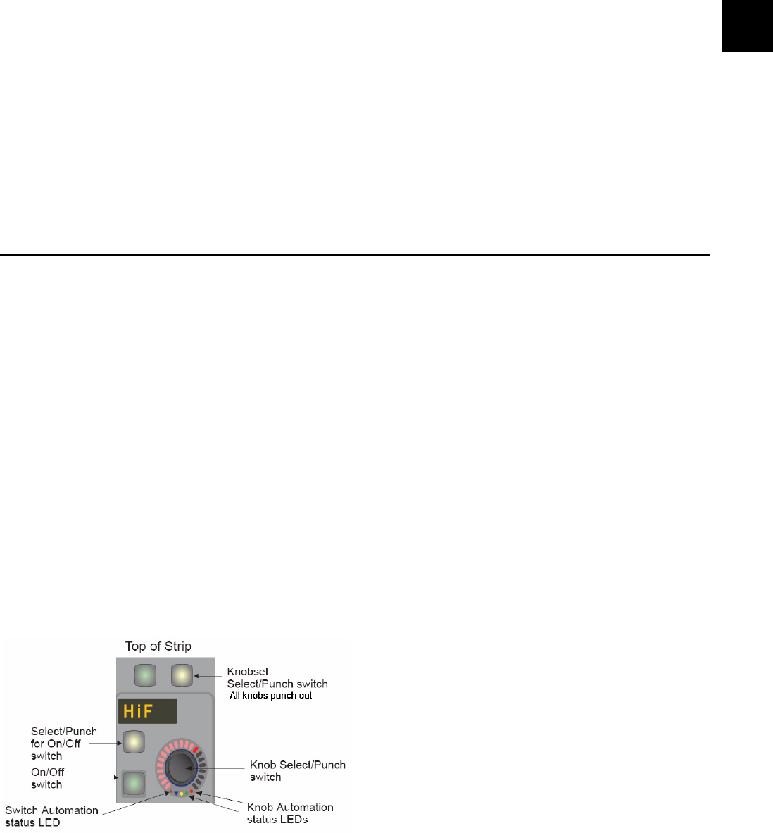
Rotary Knobs
Each Strip has eight illuminated, rotary knobs each with a four-character display and two switches. The knob is a continuous con-
troller: as the knob turns, the LEDs on the outer ring light to show the current level. The LCD shows the knob’s current function
except while touching the knob, when it shows the knob’s parameter value.
The lower switch to the left of the knob toggles the knob’s function in/out.
Rotary Knob Controls