
User guide


Table Of Contents
- Contents
- Introduction to System 5
- Master Facilities and Channel Strip
- Control, Layouts and Snapshots, and Linking
- Chapter 8: Machine Control (S5P Only)
- Chapter 9: Control Groups and Multi Format Masters
- Chapter 10: Layouts and Snapshots
- Chapter 11: Linking (S5P Only)
- Chapter 12: Dynamic Automation (S5P Only)
- Chapter 13: GPI/O Event System
- Chapter 14: CM403 Film/Post Module (S5 Only)
- Chapter 15: Hybrid Pilot and System 5 Fusion Options
- Appendix A: Compliance Information
System 5 Digital Audio Mixing System User Guide18
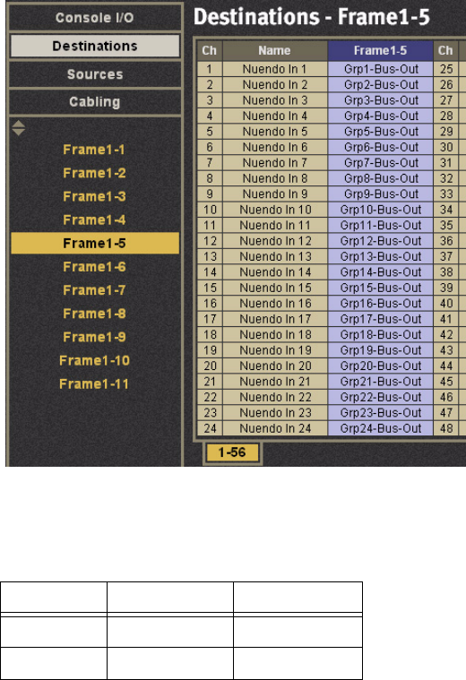
Normalled Connections
Inputs and outputs that require normalled connections must be designated in PatchNet and saved to the Title Defaults.
In the figure below, the console Group Bus outputs 1–24 should be patched to the DAW inputs. The figure below shows the Nu-
endo inputs patched from the Group Bus outputs.
If a Source is normalled to multiple destinations, <MULT> appears in the cell next to the source.
Layouts
The following table shows a typical Layout.
Meter Presets
The following are useful meter presets:
• All meters single; follow fader
• All meters single; Group Bus Outputs
• All meters single; Mix Bus Outputs
• All meters single; Aux Sends
• 1–24 Dual: Fader + Group Bus 1–24
Destinations normalled
Main Swap
Strips 1–24 Channels 1–24 Channels 25–48
Strips 25–28 Channels 49–72 Channels 73–96