
User guide


Table Of Contents
- Contents
- Introduction to System 5
- Master Facilities and Channel Strip
- Control, Layouts and Snapshots, and Linking
- Chapter 8: Machine Control (S5P Only)
- Chapter 9: Control Groups and Multi Format Masters
- Chapter 10: Layouts and Snapshots
- Chapter 11: Linking (S5P Only)
- Chapter 12: Dynamic Automation (S5P Only)
- Chapter 13: GPI/O Event System
- Chapter 14: CM403 Film/Post Module (S5 Only)
- Chapter 15: Hybrid Pilot and System 5 Fusion Options
- Appendix A: Compliance Information
Chapter 14: CM403 Film/Post Module (S5 Only) 167
The PEC/DIR Panel
This panel houses the traditional paddles used for PEC/DIR, Bus/Playback, or Bus/Tape switching. The second set of paddles are
used to put tracks into record. There are eight paddle strips, with associated switches above them, and a master control strip.
Bus/Tape switching on the paddles is consistent with the Dir/Ret CR Source switching on the CM401T (see “Monitoring” on
page 40) between the Mix busses and their associated returns. However, it is possible to switch not only the whole bus section,
but also the individual busses (legs).
By default, each mix bus section is assigned to a paddle. The master simply controls all linked bus sections at once: press the On
switch on the master, and all linked On switches turn On. The bus section name appears in the four-character display. All op-
erations take place within the monitor matrix and affect only the main CR monitors.
Turn a section On and it is sent to the monitors (same as the CM401T monitor section). Solo a section and anything currently as-
signed to the main monitors is removed, leaving only the soloed section. The bus section Bus/Playback switch toggles between
listening to the mix busses and their associated returns. The Ready switch enables dropping the tracks associated with the bus sec-
tion into record using the record paddle.
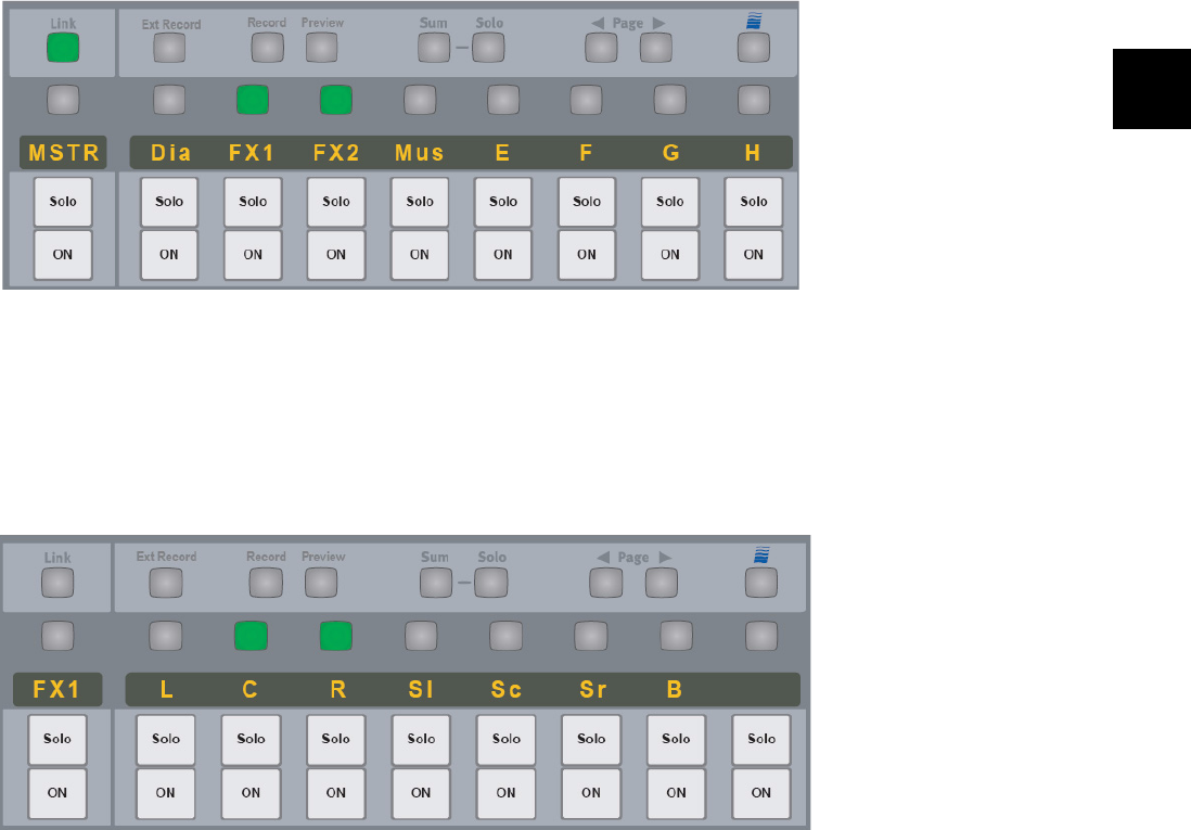
Link Key
When the Link key is lit, the user can select which sections to link to the master strip paddles and switches. For example, in the
figure above, only the FX1 and FX2 sections are affected by the master controls.
When the Link key is not lit, the keys directly above the display descend a level. This means that the busses within the selected bus
section are now assigned to the paddles, and the master strip becomes the selected bus section strip.
The same functionality applies when the Link key is not lit, except the individual busses are accessed.
The Link operation also still applies; the user dictates which busses within the section would be affected by the master. Here the
C and the R busses are lit to indicate they are linked to the master strip.
Press the Exp/Sel key on the master strip to return the panel to the top level again.
Link Key Lit
Link Key Not Lit