
User guide


Table Of Contents
- Contents
- Introduction to System 5
- Master Facilities and Channel Strip
- Control, Layouts and Snapshots, and Linking
- Chapter 8: Machine Control (S5P Only)
- Chapter 9: Control Groups and Multi Format Masters
- Chapter 10: Layouts and Snapshots
- Chapter 11: Linking (S5P Only)
- Chapter 12: Dynamic Automation (S5P Only)
- Chapter 13: GPI/O Event System
- Chapter 14: CM403 Film/Post Module (S5 Only)
- Chapter 15: Hybrid Pilot and System 5 Fusion Options
- Appendix A: Compliance Information
Chapter 13: GPI/O Event System 163
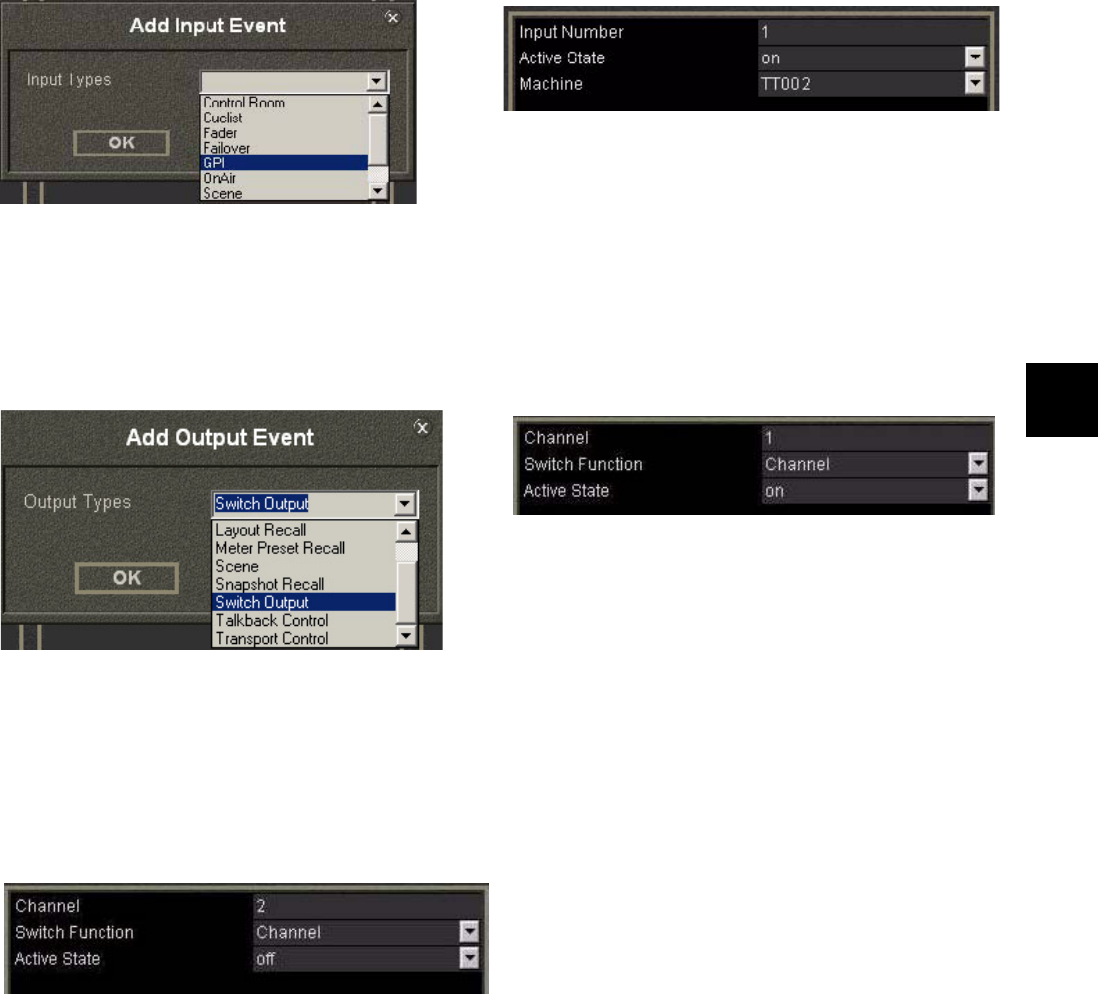
3 From the Inputs section, click <click to add input>.
The Add Input Event dialog opens.
4 Select GPI from the Input Types menu.
5 Configure the lower area of the Input section to the settings in the figure above (right).
6 From the Output section, click <click to add output event>.
The Add Output Event dialog opens.
7 Select Switch Output from the Output Type menu.
8 Configure the lower area of the Output section to the settings in the figure above (right).
This turns channel 1 on when camera 1 is selected by the video switcher.
9 Repeat Steps 6–7 to create additional output events to mute channels 2–4, but use the following settings instead of those from
Step 8:
The figure above shows Channel 2’s settings. Each channel uses its own number but Switch Function = Channel and Active State
= off for each.
Now when the video switcher selects camera 1, System 5’s channel 1 turns on and channels 2–4 mute.
Repeat the steps above to program channel 2 to turn on when the video switcher selects camera 2, and mute channels 1, 3, and
4. Each tally input requires a discrete connection at the GPIO card at the System PC.
Add Input Event Dialog (left) and Input Events Properties (right)
Add Output Event dialog (left) and Output Events Properties (right)
Output Events Properties to mute channels 2-4