
User guide


Table Of Contents
- Contents
- Introduction to System 5
- Master Facilities and Channel Strip
- Control, Layouts and Snapshots, and Linking
- Chapter 8: Machine Control (S5P Only)
- Chapter 9: Control Groups and Multi Format Masters
- Chapter 10: Layouts and Snapshots
- Chapter 11: Linking (S5P Only)
- Chapter 12: Dynamic Automation (S5P Only)
- Chapter 13: GPI/O Event System
- Chapter 14: CM403 Film/Post Module (S5 Only)
- Chapter 15: Hybrid Pilot and System 5 Fusion Options
- Appendix A: Compliance Information
Chapter 12: Dynamic Automation (S5P Only) 127
Automation LEDs
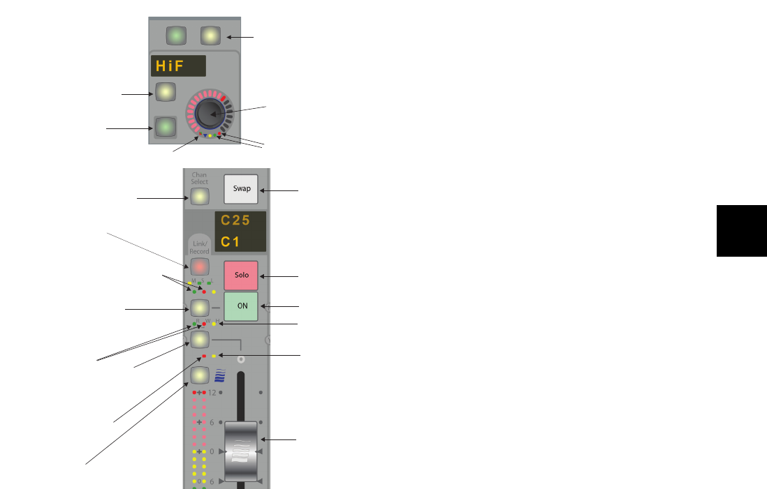
The figure below shows the fader, switch, and knob automation interfaces. Each automated parameter has two status LEDs:
• The red LED (right) indicates the parameter is in Write mode.
• The green LED (left) indicates the parameter is in Read mode.
Select/Punch Keys
The Select/Punch keys
• punch the control into and out of recording automation;
– and –
• assign the selected automation mode to its corresponding parameter.
Knob (top) and fader (bottom) automation and control features
Chan
Select
Fader Automation
Status LEDs
Fader Select/Punch key
Select/Punch key
Channel On
Channel On
Automation status LEDs
Strip Lock LED
Wave key
All Funcs key
Select/Punch
for On/Off
switch
Knob Select/Punch
switch
Knob Automation
status LEDs
Switch Automation
status LED
On/Off
switch
Knobset
Select/Punch switch
Top of Strip
Channel Select
key
Swap channel
key
Solo
key
Channel On key
Auto-glide LED
Fader touch-
sensor LED
Touch-sensitive
fader