
User guide
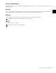


Table Of Contents
- Contents
- Introduction to System 5
- Master Facilities and Channel Strip
- Control, Layouts and Snapshots, and Linking
- Chapter 8: Machine Control (S5P Only)
- Chapter 9: Control Groups and Multi Format Masters
- Chapter 10: Layouts and Snapshots
- Chapter 11: Linking (S5P Only)
- Chapter 12: Dynamic Automation (S5P Only)
- Chapter 13: GPI/O Event System
- Chapter 14: CM403 Film/Post Module (S5 Only)
- Chapter 15: Hybrid Pilot and System 5 Fusion Options
- Appendix A: Compliance Information
System 5 Digital Audio Mixing System User Guide94
Mix Bus
Press the Mix Mstrs key to assign the mix bus sections to the Bus Master knobset. The Master Fader controls the overall Mix sec-
tion levels. Each Mix section has its own level control as well as trim controls for each Mix Bus in its selected format. (See “Bus-
ses” on page 26 to see how to set the format.) Relative levels are maintained when adjusting the Mix Bus Master or Mix Bus sec-
tion level until a maximum or minimum value is reached.
The left side of the figure above shows the Mix Bus Master display after pressing the Mix Mstrs button (or the top-right knobset
function key next to Clear). The important functions are summarized below:
• Press the upper of the two buttons to the left of each knob to display the individual busses for that Mix Section.
• Adjust the knob to control the Mix Bus overall level.
• Press a knob to display individual Section meters on the TFT screen.
• Press the lower of the two buttons to the left of each knob to turn that Mix Bus On/Off. All individual bus parameters are re-
tained if the Bus is turned on after being off.
•Use the and buttons to display additional pages if there are more than eight busses.
Mix Bus Master (left) and Individual Bus (right) Displays