
Installation Manual


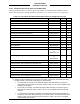


Table Of Contents
- 17001_0_Frt-Matr
- 17001_1_Gen-Info
- 1.1 INTRODUCTION
- 1.2 FUNCTIONAL DESCRIPTION
- 1.2.1 Software Release Summary
- 1.2.2 Transponder Functional Overview
- 1.2.3 GPS Functional Overview
- 1.2.4 Lightning Detection (optional)
- 1.2.5 ADS-B System Overview
- 1.2.6 Traffic Display Functional Overview
- 1.2.7 FISB System Overview
- 1.2.8 Traffic Awareness System (option) Overview
- 1.2.9 ADS-B Traffic Advisory System Overview (optional)
- 1.2.10 Traffic Alert and Collision Avoidance System (option) Overview
- 1.2.11 Terrain Awareness and Warning System Overview (optional)
- 1.2.12 TerrainVisionTM
- 1.2.13 Discrete Inputs and Outputs Functional Overview
- 1.3 EQUIPMENT DESCRIPTIONS
- 1.4 INTERFACES
- 1.4.1 ADS-B Out Fail
- 1.4.2 AHRS Input
- 1.4.3 Altitude Encoder Input
- 1.4.4 Audio Out
- 1.4.5 Standby Mode
- 1.4.6 Audio Mute In and Out
- 1.4.7 Audio Acknowledge
- 1.4.8 RF Suppression Input/output
- 1.4.9 Traffic Alert
- 1.4.10 TAWS Caution and Warning Alert
- 1.4.11 WiFi Interface
- 1.4.12 WOW Input
- 1.4.13 Maintenance Interface
- 1.4.14 GPS Antenna
- 1.4.15 L-Band (978/1030/1090 MHz) Antenna
- 1.4.16 Directional Antenna
- 1.4.17 Traffic Display
- 1.4.18 Weather Display
- 1.4.19 Lightning Detection (WX-500)
- 1.4.20 Control Panel
- 1.5 INSTALLATION CONSIDERATIONS
- 1.6 SPECIFICATIONS
- 1.7 TSO INFORMATION
- 1.8 MODIFICATIONS
- 1.9 SOFTWARE REVISIONS
- 1.10 EQUIPMENT REQUIRED NOT SUPPLIED
- 1.11 EQUIPMENT INTERFACES
- 1.12 OBTAINING SOFTWARE
- 1.13 INSTALLATION PROCEDURE FOR LYNXMSS USB DRIVER
- 1.14 INSTALLATION APPROVAL AND LIMITATIONS
- 17001_2_Instal
- 2.1 INTRODUCTION
- 2.2 UNPACKING AND INSPECTING
- 2.3 INSTALLATION PROCEDURES
- 2.3.1 Panel Mount Location
- 2.3.2 Remote Mount Location
- 2.3.3 Electrical Connections
- 2.3.4 Compatible Equipment Installation Information
- 2.3.5 Discrete Inputs and Output Connections
- 2.3.6 Installation Guidelines for the DCM
- 2.3.7 P1 Mating Connector Assembly
- 2.3.8 Panel mount NGT-9000 Installation
- 2.3.9 Remote Mounted Lynx NGT-9000 Installation
- 2.3.10 CP-2500 Installation Guidelines
- 2.3.11 Antenna Installation Guidelines
- 17001_3_Inst_Check
- 3.1 INTRODUCTION
- 3.2 BASIC OPERATION
- 3.3 MPC (MAT) OPERATION
- 3.4 INSTALLATION PROCEDURE FOR LYNXMSS USB DRIVER
- 3.5 MAINTENANCE MODE
- 3.6 VERIFY SOFTWARE VERSION
- 3.7 SELECT CONFIGURATION OPTIONS
- 3.8 CALIBRATION SETUP
- 3.9 INTERFACE CHECK
- 3.10 SETUP PIM-9000 WIFI MODULE
- 3.11 INSTALLATION CHECKOUT
- 3.11.1 Functional Checks
- 3.11.2 Ground Checks
- 3.11.3 Electromagnetic Interference (E.M.I.) Check
- 3.11.4 Panel mount NGT-9000 Display Check
- 3.11.5 Flight Test
- 3.11.6 Installation Checkout Complete
- 17001_4_Maint
- 17001_5_App-A_signal
- A.1 INTRODUCTION
- A.2 INPUT AND OUTPUT INTERFACES
- A.2.1 Input Power
- A.2.2 RF Suppression Bus
- A.2.3 Audio Output
- A.2.4 Gillham Input (Altitude Input)
- A.2.5 RS-232 Interface
- A.2.6 RS-422 Interface
- A.2.7 ARINC 429 Input
- A.2.8 ARINC 429 Output
- A.2.9 Discrete Input
- A.2.10 Discrete Output
- A.2.11 I2C Serial Bus (Detachable Configuration Module)
- A.2.12 Antenna Connections
- A.3 PIN DEFINITION SUMMARY
- A.4 [J1 CONNECTOR]
- 17001_6_App-B_Environmental
- 17001_7_App-C_Compatibility
- 17001_8_App-D_TSO
- 17001_9_App-E_Questionaire

Lynx NGT-9000
Installation Manual
0040-17001-01 (Revision W) General Information Page 1-39
Table 1-18: Pre-Fabricated Coaxial Cable Assemblies
PART NUMBER DESCRIPTION SPECIFICATIONS
9020-17008-01 Cable Assembly, Straight Plug with TNC Jack
Length: 8.00 +/- 0.50 inches
Max Loss: 0.50 dB
Max VSWR: 1.5:1
9020-17009-01 Cable Assembly, Straight Plug with BNC Jack
9020-17010-01 Cable Assembly, Right Angle Plug with TNC Jack
9020-17011-01 Cable Assembly, Right Angle Plug with BNC Jack
Table 1-19: Directional Antenna SIGMA and DELTA Port Cable Vendors
Manufacturer: Electrical and Mechanical Technologies (EMTEQ)
Part Number Attenuation
(dB/100 ft. 1.0 GHz)
Weight (lb.)
(per 100 ft.)
Maximum
Length (ft.)
Minimum Bend
Radius (in)
Polyethylene
PFLX195-500
10.93
2.6
10
0.50
PFLX240-500
8.79
3.8
12
0.75
PFLX240-501
7.9
4.5
13
0.85
PFLX340-500
5.25
7.4
20
1.00
PFLX400-500
4.0
6.8
27
1.00
PFLX500-500
3.31
11.8
35
1.25
Teflon
TFLX130-100
16.7
1.4
6
0.50
TFLX165-100
13.8
2.2
8
0.85
TFLX205-100
9.9
3.2
11
0.75
TFLX225-100
7.9
4.1
14
2.0
TFLX295-100
5.95
7.2
18
1.5
TFLX480-100
3.5
19
31
4.5
Frequency: 1030 MHz Loss: <1.5 dB at 1030 MHz (includes all cables and connectors)
VSWR: <1.5:1 at 1030 MHz Connectors have 0.2dB loss each
Manufacturer: Carlisle IT
Part Number
Attenuation
(dB/100 ft. 1.0 GHz)
Weight (lb.)
(per 100 ft.)
Maximum
Length (ft.)
Minimum Bend
Radius (in)
352001
12.2
2.7
9
0.81
311601
8.7
5.5
12
1.15
311201
5.56
8.5
19
1.59
310801
3.63
16.1
30
2.26
Manufacturer: PIC Wire and Cable
Part Number
Attenuation
(dB/100 ft. 1.0 GHz)
Weight (lb.)
(per 100 ft.)
Maximum
Length (ft.)
Minimum Bend
Radius (in)
S33141
7.2
6.5
15
1.5
S55122
5.7
8.2
19
1.6
S22089
3.8
18
29
2.5
NOTE
If cable weight is not a consideration, select lowest loss cable. Contact cable
vendors before installation. New low-loss lightweight cables may be available.